Device and method for adjusting deflector angle of scr reactor

An SCR reactor and angle adjustment technology, applied in chemical instruments and methods, separation methods, gas treatment, etc., can solve the problem that the SCR reactor cannot be adjusted according to the working conditions, so as to reduce the phenomenon of boundary layer separation, reduce the adjustment time, The effect of reducing the area

Active Publication Date: 2021-03-30
SOUTH CHINA UNIV OF TECH
View PDF9 Cites 0 Cited by
  • Summary
  • Abstract
  • Description
  • Claims
  • Application Information

AI Technical Summary

Problems solved by technology

[0006] The purpose of the present invention is to overcome the technical defect that the traditional SCR reactor cannot be adjusted according to the working conditions, and to provide an SCR deflector adjusting device

Method used


Image

  • Device and method for adjusting deflector angle of scr reactor
  • Device and method for adjusting deflector angle of scr reactor
  • Device and method for adjusting deflector angle of scr reactor

Examples


Embodiment

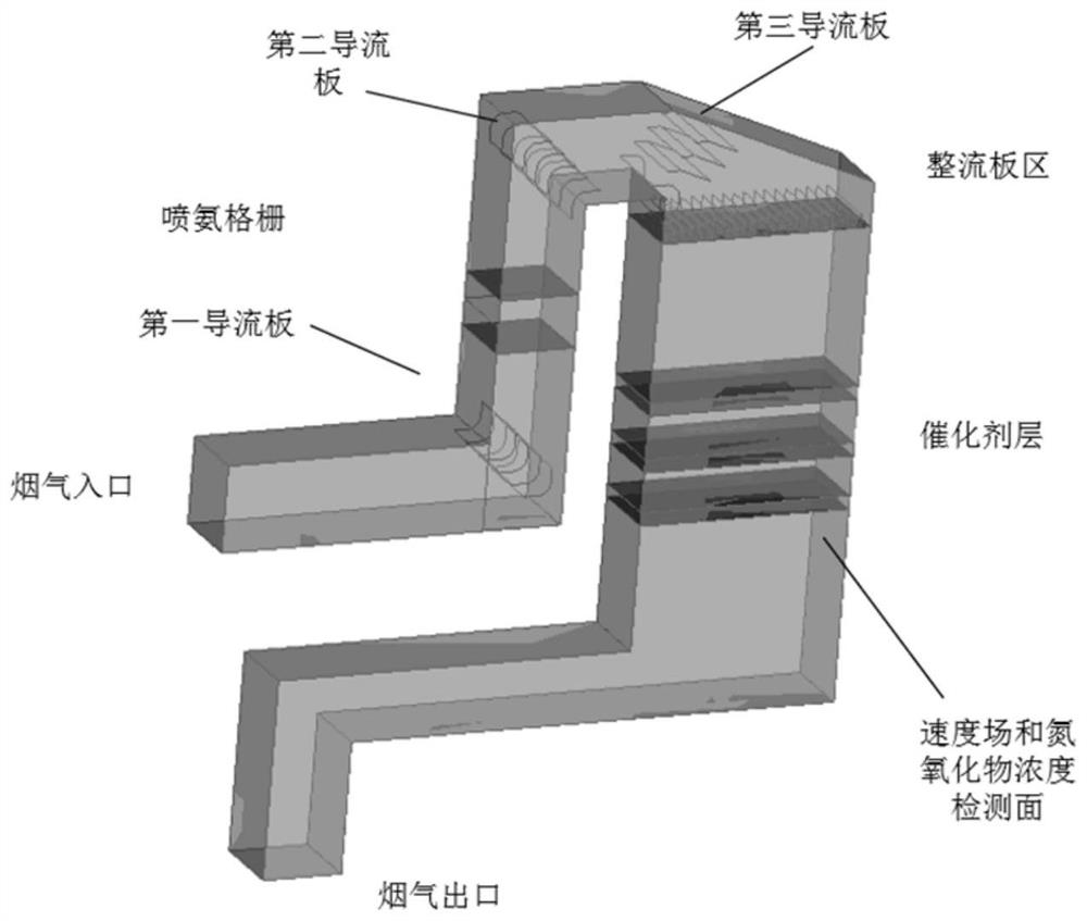
[0046] Such as figure 1 Shown is a schematic structural diagram of an SCR deflector adjusting device, in which a first deflector, a second deflector and a third deflector are sequentially arranged at three bends of the SCR reactor flue; The deflectors are all arranged at the geometric center of the curve; the area between the first deflector and the second deflector is provided with an ammonia injection grid; the area between the third deflector and the flue gas outlet is provided with a catalyst layer; A number of rectifying plates are arranged above the uppermost catalyst layer, and a nitrogen oxide detection system and a velocity measurement system are arranged below the lowermost catalyst layer;

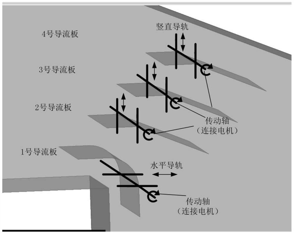
[0047] Such as figure 2 Shown is a schematic diagram of the angle adjustment structure and the position adjustment structure in the third deflector, such as image 3 Shown is a partially enlarged schematic diagram of the third deflector. Each deflector of the third deflector ...

Embodiment 2

[0066] This embodiment provides a method for optimizing the adjustment strategy of the deflector based on CFD. Provide basis for structure adjustment and relative position adjustment of deflector, such as Image 6 with Figure 7 Shown are the flow chart of the method for adjusting the SCR deflector and the flow chart of computational fluid dynamics (CFD) simulation, respectively. The method comprises the steps of:

[0067] Optimize the structural parameters of the deflector through fluid dynamics (CFD) calculations;

[0068] Construct the physical model and grid model of the SCR reactor and the deflector according to the structural parameters and basic shape of the deflector;

[0069] The parameters of the actual operating conditions are input into the solver, and the velocity field distribution of the SCR reactor is simulated by numerical calculation.

[0070] Take the typical flue gas composition as an example as the boundary condition: the outlet flue gas composition is...


PUM


Abstract

The invention discloses an SCR flow guide plate adjusting device. A first flow guide plate, a second flow guide plate and a third flow guide plate are sequentially arranged at three bends of an SCR reactor flue; the three guide plates are arranged at the geometric centers of the bends; an ammonia spraying grid is arranged in an area between the first flow guide plate and the second flow guide plate; a catalyst layer is arranged in an area between the third guide plate and a flue gas outlet; a plurality of rectifying plates are arranged above the catalyst layer, and a nitrogen oxide detection system and a speed measurement system are arranged below the catalyst layer; each guide plate of the third guide plate is provided with an angle adjusting mechanism and a position adjusting mechanism,and each angle adjusting mechanism comprises an angle adjusting motor; each position adjusting mechanism comprises a position adjusting motor; and the angle adjusting motor and the position adjustingmotor are connected with a control system. The guide plate adjusting device provided by the invention can adjust the uniformity of the flow field of a SCR reactor according to the adjustment of the load and the operation condition of a thermal power plant.

Description

technical field [0001] The invention relates to the field of selective catalytic reduction (SCR) in thermal power plants, in particular to an SCR reactor guide plate angle adjustment device and a control method thereof. Background technique [0002] Nitrogen oxides are one of the main pollutants of air pollution, which will harm the ecosystem and human health. Selective Catalytic Reduction (SCR), as the most mature nitrogen removal technology in thermal power plants, has been widely used. Due to the complex flow field of the SCR reactor, there are many sharp bends to form a vortex zone, which reduces the denitrification efficiency and is not conducive to the stable operation of the reactor. [0003] The principle of Selective Catalytic Reduction (SCR) is mainly to convert nitrogen oxides into N 2 and H 2 O. The denitrification reaction mainly includes the following processes: [0004] The uniformity of the flue gas entering the SCR catalyst layer greatly affects the cat...

Claims


Application Information

Patent Timeline
Patent Type & Authority Patents(China)
IPC IPC(8): B01D53/90B01D53/56B01D53/86
CPCB01D53/8631B01D53/8696B01D53/90B01D2258/0283
Inventor 王海川廖艳芬曾祥浩马晓茜郑楚鹏
Owner SOUTH CHINA UNIV OF TECH
Why Eureka
Try Eureka