
Battery module and heat dissipation device thereof

A battery module and cooling device technology, applied to battery pack parts, secondary batteries, circuits, etc., can solve problems such as poor heat dissipation, hot battery, and influence on battery current distribution, so as to enhance heat conversion capability and reduce Working temperature, the effect of ensuring the working environment

Pending Publication Date: 2020-04-24
GUANGDONG MAXON COMM
View PDF5 Cites 0 Cited by
  • Summary
  • Abstract
  • Description
  • Claims
  • Application Information

AI Technical Summary

Problems solved by technology

[0002] The battery will generate a certain amount of heat in the process of charging and discharging, especially in the process of charging and discharging with high current, a large amount of heat will be generated inside the battery, and a large amount of accumulated heat will generate a serious temperature gradient inside the battery, affecting the internal current of the battery The distribution of the battery leads to the inconsistency of the internal attenuation of the battery, which seriously affects the service life of the battery. Therefore, setting up a battery cooling device is of great significance to the long-term use of the battery.
[0003] In order to prevent the temperature of the battery from being too high during charging and discharging, the battery is often used with a heat sink. The current common heat dissipation method is to install the heat sink on the protective shell of the battery module. However, in order to prevent rainwater and other sundries from directly contacting the battery, the protection The shell is often closed, which makes it difficult for the internal heat to pass through quickly. The heat transfer efficiency is low when it is close to the heat sink. Long-term use will still cause problems such as battery heating, and the actual heat dissipation effect is poor.

Method used


Image

  • Battery module and heat dissipation device thereof
  • Battery module and heat dissipation device thereof
  • Battery module and heat dissipation device thereof

Examples


Embodiment Construction

[0021] In order to make the technical means, creative features, goals and effects achieved by the present invention easy to understand, the present invention will be further described below in conjunction with specific embodiments.

[0022] In the description of the present invention, it should be noted that the terms "upper", "lower", "inner", "outer", "front end", "rear end", "both ends", "one end", "another end" The orientation or positional relationship indicated by etc. is based on the orientation or positional relationship shown in the drawings, and is only for the convenience of describing the present invention and simplifying the description, rather than indicating or implying that the referred device or element must have a specific orientation, use a specific Azimuth configuration and operation, therefore, should not be construed as limiting the invention. In addition, the terms "first" and "second" are used for descriptive purposes only, and should not be understood ...


PUM


Abstract

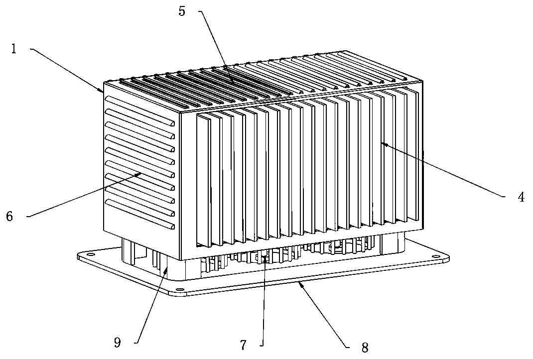
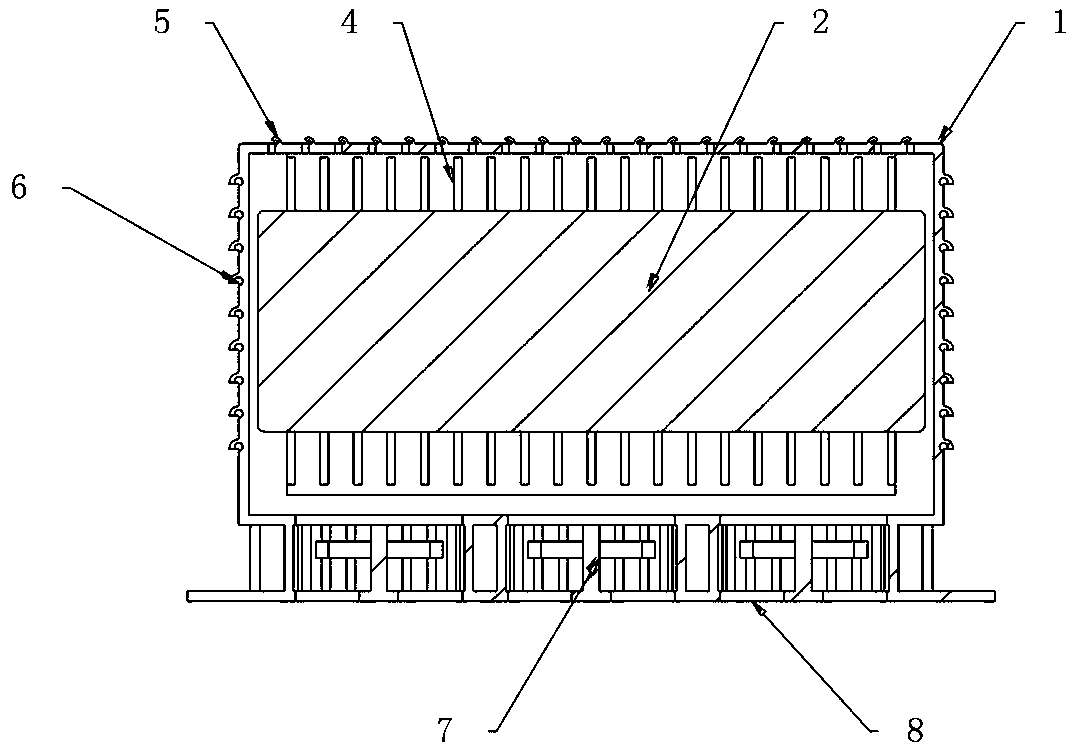
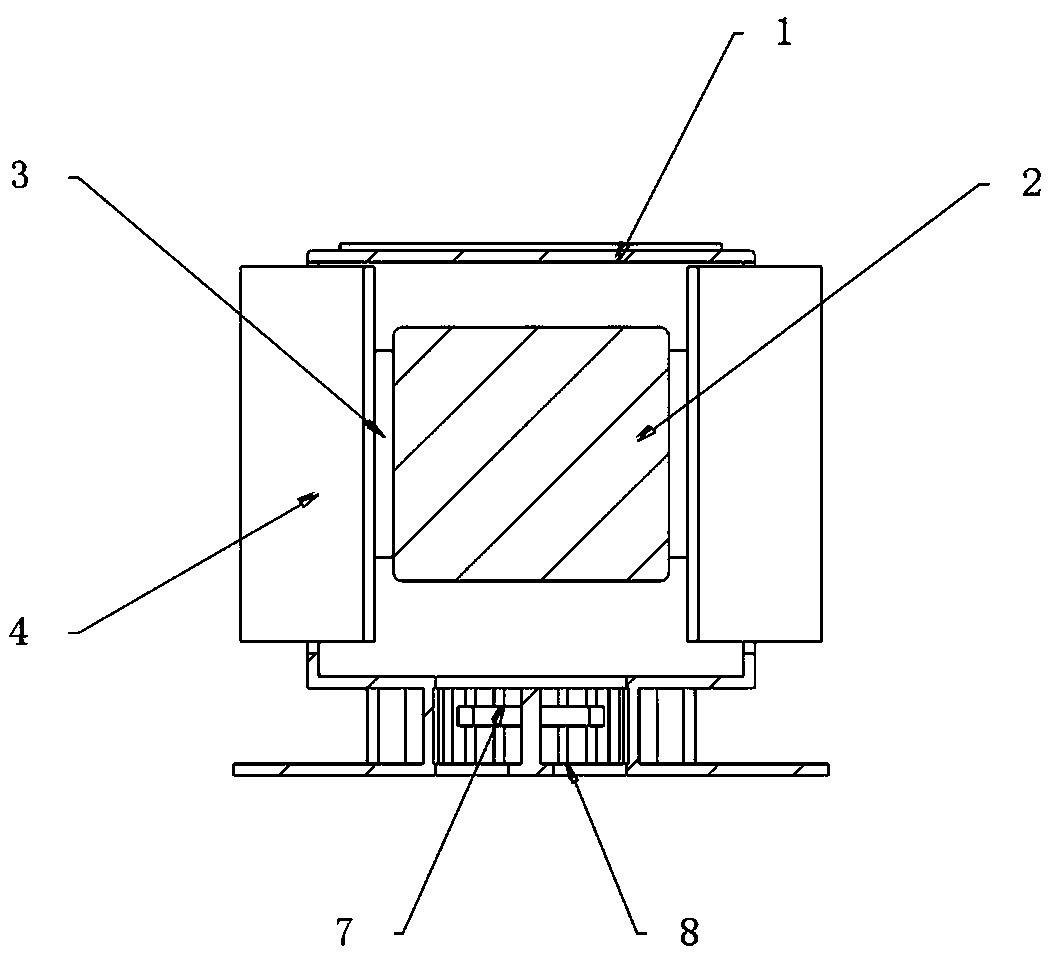
The invention discloses a battery module and a heat dissipation device thereof. The battery module comprises a protective shell and a battery module, and the battery module is arranged in the protective shell. Fixing seats are symmetrically arranged at the front end and the rear end of the battery module, and a plurality of uniformly distributed cooling fins are arranged at the front ends of the fixing seats. The front end and the rear end of the protective shell are designed to be hollow, and the cooling fins penetrate through the protective shell. A plurality of uniformly distributed top heat dissipation openings are formed in the top end of the protective shell, the top heat dissipation openings comprise heat dissipation openings, and waterproof convex strips are arranged at the right ends of the heat dissipation openings. The fixing seats and the cooling fins are integrally formed by a copper-aluminum alloy material, the heat-conducting property of the copper-aluminum alloy material is excellent, the front end and the rear end with the most obvious heating of the battery module are directly fixed through the fixing seats, and heat-conducting silicone grease is arranged at the contact positions, so that the heat-conducting property of the device is greatly improved, the working temperature of the battery module is reduced, and the service life of the battery module is prolonged.

Description

technical field [0001] The invention relates to the technical field of battery equipment, in particular to a battery module and a heat dissipation device thereof. Background technique [0002] The battery will generate a certain amount of heat in the process of charging and discharging, especially in the process of charging and discharging with high current, a large amount of heat will be generated inside the battery, and a large amount of accumulated heat will generate a serious temperature gradient inside the battery, affecting the internal current of the battery The distribution of the battery leads to the inconsistency of the internal attenuation of the battery, which seriously affects the service life of the battery. Therefore, setting up a battery cooling device is of great significance to the long-term use of the battery. [0003] In order to prevent the temperature of the battery from being too high during charging and discharging, the battery is often used with a he...

Claims


Application Information

Patent Timeline
IPC IPC(8): H01M10/613H01M10/653H01M10/6551H01M10/6563H01M2/10
CPCH01M10/613H01M10/653H01M10/6551H01M10/6563H01M50/20Y02E60/10
Inventor 马建华雷志春邱维毅傅海鹏安文星
Owner GUANGDONG MAXON COMM
Learn More