Fuel injector

A fuel injector and gaseous fuel technology, which is applied to fuel injection devices, special fuel injection devices, fuel injection valves driven by fluid pressure, etc. Assembly effect

Pending Publication Date: 2020-04-24
ROBERT BOSCH GMBH
View PDF12 Cites 0 Cited by
  • Summary
  • Abstract
  • Description
  • Claims
  • Application Information

AI Technical Summary

Problems solved by technology

However, the regulation of the gas pressure by means of such a pressure regulator takes place very slowly due to the high compressibility of the gaseous fuel
Furthermore, a large control flow is generated, which is lost because it can neither be led back into the gas tank nor supplied for combustion due to the low pressure level

Method used


Image

  • Fuel injector
  • Fuel injector
  • Fuel injector

Examples


Embodiment Construction

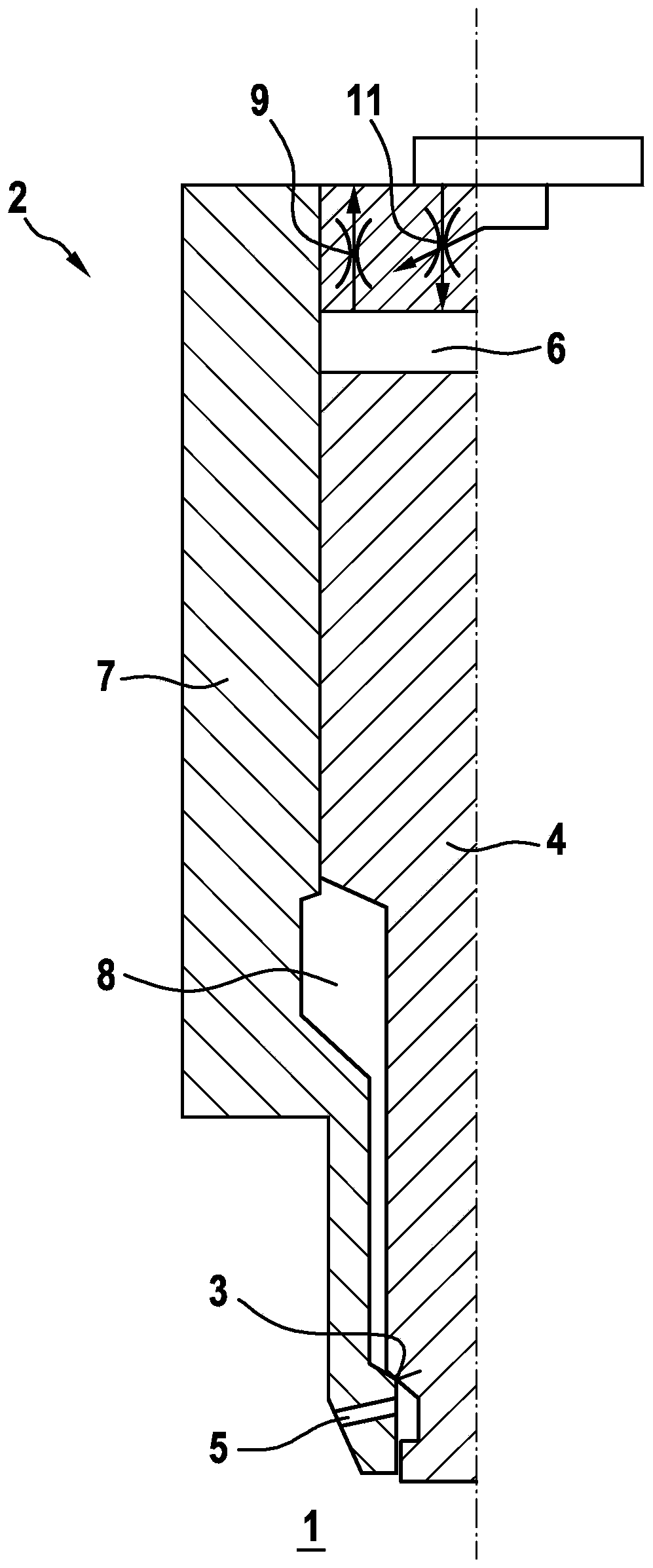
[0039] exist figure 1 The fuel injector 2 shown partially in the center comprises a nozzle body 7 which forms the sealing seat 3 for the reciprocating nozzle needle 4 . The blow-in opening 5 formed in the nozzle body 7 can be released or closed by the reciprocating movement of the nozzle needle 4 . With the nozzle needle 4 raised, gaseous fuel, for example natural gas, flows from the pressure chamber 8 formed between the nozzle body 7 and the nozzle needle 4 in the direction of the injection opening 5 and via the injection opening 5 to the Combustion chamber 1 of an internal combustion engine.

[0040] To open the nozzle needle 4 , the control pressure is reduced in the control chamber 6 above the nozzle needle 4 , which is acted upon by the hydraulic pressure medium. The control pressure acting on the nozzle needle 4 produces a hydraulic closing force which holds the nozzle needle 4 in the sealing seat 3 . For opening, the control pressure in the control chamber 6 is reduc...


PUM


Abstract

The invention relates to a fuel injector (2) for injecting gaseous fuel into a combustion chamber (1) of an internal combustion engine, the invention relates to a fuel injector (1) comprising at leastone reciprocally movable nozzle needle (4) which interacts with a sealing seat (3) for releasing and closing at least one injection opening (5), said nozzle needle (4) delimiting a control chamber (6) which can be acted upon with a hydraulic pressure medium, preferably a liquid fuel, via an inflow throttle (11). According to the invention, the inflow throttle part (11) has a variable throttle cross-sectional area. Wherein the control chamber (6) is designed in such a way that the flow of hydraulic pressure medium into the control chamber (6) can control the opening speed of the nozzle needle(4) as a function of the load, wherein the variable throttle cross-sectional area is formed by at least one opening (16) of a sleeve (20), in which a piston (12) is mounted and guided in a reciprocally movable manner in order to control the at least one opening (16).

Description

technical field [0001] The invention relates to a fuel injector for blowing a gaseous fuel, for example natural gas (NG: Natural Gas, that is to say “petroleum gas”), into a combustion chamber of an internal combustion engine. [0002] The fuel injectors may be configured as single fuel injectors or as dual fuel injectors. In the case of a dual fuel injector, the fuel injector can be used to inject or inject two different fuels, for example a gaseous fuel and a liquid fuel. For example, gaseous fuels can be ignited by means of liquid fuels. This applies in particular where diesel fuel is used as the liquid fuel. Background technique [0003] In the combustion of gaseous fuels, higher and higher injection pressures are achieved in order to meet the requirements at full load as are imposed for the combustion of diesel fuel. However, a high injection pressure leads to an injection rate which is too high at partial load of the internal combustion engine and which is often acc...

Claims


Application Information

Patent Timeline
Patent Type & Authority Applications(China)
IPC IPC(8): F02M47/02F02M61/10F02M21/02F02M43/04
CPCF02M47/025F02M61/10F02M21/0263F02M21/0251F02M43/04F02M21/0215F02M21/0275F02M2547/008F02M2200/28Y02T10/30
Inventor M·卡茨B·莱布斯勒J·韦斯内尔
Owner ROBERT BOSCH GMBH
Why Eureka
Try Eureka