
Exhaust utilization system of gas turbine

A gas turbine and airframe technology, which is applied to gas turbine devices, mechanical equipment, engine components, etc., can solve the problems of high noise pollution, waste of kinetic energy, and large exhaust speed of gas turbines, and achieve high-efficiency cooling, noise reduction, and low carbon dioxide emissions. Effect

Active Publication Date: 2020-04-24
ZHEJIANG TUFF BOILER
View PDF6 Cites 4 Cited by
  • Summary
  • Abstract
  • Description
  • Claims
  • Application Information

AI Technical Summary

Problems solved by technology

[0002] The gas turbine is an internal combustion power machine that uses continuous flowing gas as the working medium to drive the impeller to rotate at high speed, and converts the energy of the fuel into useful work. Small size, light weight, fast start-up, little or no cooling water, etc., but the high exhaust velocity of the gas turbine is a waste of kinetic energy, and the noise pollution is high. At the same time, it is necessary to monitor the exhaust temperature to Know whether the internal combustion is sufficient, and the exhaust gas contains a lot of carbon dioxide, these problems need to be solved

Method used


Image

  • Exhaust utilization system of gas turbine
  • Exhaust utilization system of gas turbine
  • Exhaust utilization system of gas turbine

Examples


Embodiment Construction

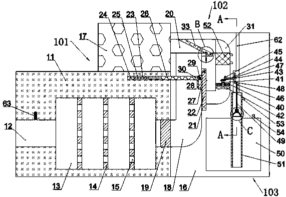
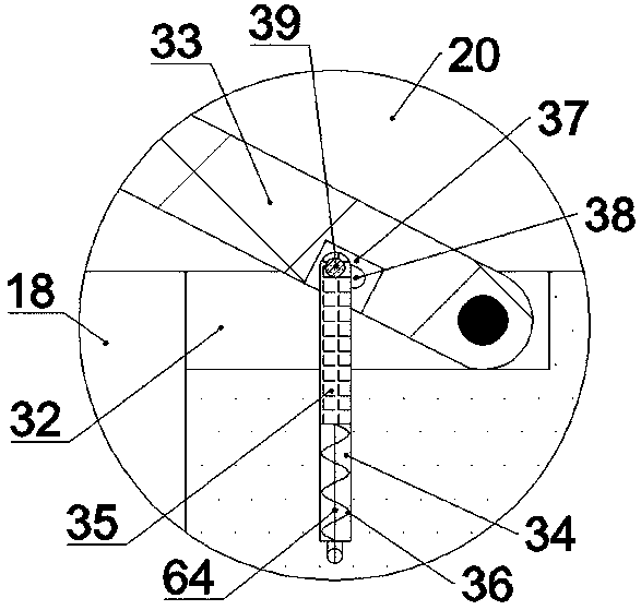
[0018] Combine below Figure 1-Figure 4 The present invention is described in detail, and for convenience of description, the orientations mentioned below are now stipulated as follows: figure 1 The up, down, left, right, front and back directions of the projection relationship itself are the same.

[0019] The present invention relates to a gas turbine exhaust utilization system, which is mainly used for processing the exhaust gas of a gas turbine. The present invention will be further described below in conjunction with the drawings of the present invention:

[0020] A gas turbine exhaust utilization system according to the present invention includes a first body 11 and an air inlet 12 arranged on the left end surface of the first body 11 and opening to the left. The first body 11 is provided with an exhaust Conveying device 101, the exhaust conveying device 101 includes a muffler cavity 13 connected to the right wall of the air intake channel 12, the inner wall of the muff...


PUM


Abstract

The invention discloses an exhaust utilization system of a gas turbine. The exhaust utilization system comprises a first machine body and an air inlet channel which is arranged on the left end surfaceof the first machine body and has an opening facing leftwards; an exhaust conveying device is arranged on the first machine body; the exhaust conveying device comprises a sound damping cavity communicating with the right wall of the air inlet channel; three baffle plates are uniformly distributed and fixedly arranged on the inner wall of the circumference of the sound damping cavity; each baffleplate is through from left to right and is uniformly provided with meshes; a second machine body is fixedly arranged on the right end surface of the first machine body; a gas path changing device is arranged in the exhaust conveying device; and an air flow cooling device is arranged in the second machine body. The system can effectively muffle exhaust gas of the gas turbine to reduce noise, compress carbon dioxide in the exhaust gas, and effectively utilize the exhaust gas. Meanwhile, a gas cooling device can be automatically started when the exhaust gas temperature rises due to insufficient combustion of the gas turbine, and the hot gas flow is efficiently cooled, so that working efficiency of a carbon dioxide compressor is prevented from being influenced, and low carbon dioxide emissionof the gas turbine is realized.

Description

technical field [0001] The invention relates to the technical field of gas turbines, in particular to a gas turbine exhaust utilization system. Background technique [0002] The gas turbine is an internal combustion power machine that uses continuous flowing gas as the working medium to drive the impeller to rotate at high speed, and converts the energy of the fuel into useful work. Small size, light weight, fast start-up, little or no cooling water, etc. However, the high exhaust velocity of the gas turbine is a waste of kinetic energy, and the noise pollution is high. At the same time, it is necessary to monitor the exhaust temperature at all times. Knowing whether the internal combustion is complete, and the exhaust contains a lot of carbon dioxide, these problems have yet to be resolved. The present invention illustrates a device capable of solving the above-mentioned problems. Contents of the invention [0003] technical problem: [0004] The high exhaust velocity ...

Claims


Application Information

Patent Timeline
Patent Type & Authority Applications(China)
IPC IPC(8): F02C6/00F02C7/24F02C7/12
CPCF02C6/00F02C7/12F02C7/24
Inventor 不公告发明人
Owner ZHEJIANG TUFF BOILER
Learn More