
Structured grid division method for rod bundle assembly with wire winding function

A technology of mesh division and component structure, applied in design optimization/simulation, image data processing, 3D modeling, etc., can solve problems such as rough surface of winding wire, achieve high mesh quality, reduce mesh number, and converge Good results

Inactive Publication Date: 2020-04-21
XI AN JIAOTONG UNIV
View PDF5 Cites 2 Cited by
  • Summary
  • Abstract
  • Description
  • Claims
  • Application Information

AI Technical Summary

Problems solved by technology

[0006] The technical problem to be solved by the present invention is to provide a structured grid division method for the belt-wound rod bundle assembly, which solves the problem of the low degree of geometric reduction of the unstructured grid. , the grid quality is poor, the space filling rate is low, and the problem of occupying a large amount of computing resources is overcome. At the same time, the problem of the rough surface of the winding wire in the mesh model generated by the "grid marking method" can be overcome, and the tape winding can be better restored. While adjusting the geometric characteristics of the wire rod bundle assembly, the grid node parameters can be flexibly adjusted to provide high-quality mesh for the CFD calculation of the wire rod bundle assembly

Method used


Image

  • Structured grid division method for rod bundle assembly with wire winding function
  • Structured grid division method for rod bundle assembly with wire winding function
  • Structured grid division method for rod bundle assembly with wire winding function

Examples


Embodiment Construction

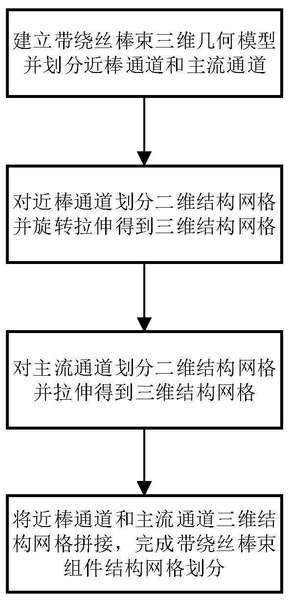
[0031] Combine below figure 1 In the flow chart shown, the present invention is further described in detail by taking the supercritical water reactor 2×2 wire-wound fuel assembly as an example. Specifically include the following steps:

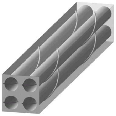
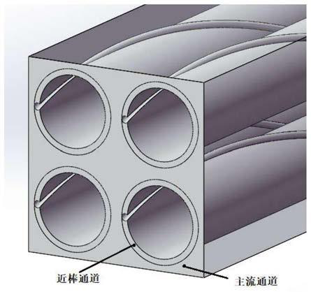
[0032] Step 1: Establish a three-dimensional geometric model of the supercritical pressurized water reactor with wire-wound 2×2 rod bundle components. When modeling, the geometric characteristics of the wire-wound need to be established. In this example, the length of the calculation area selected is 300mm, and the length of the two wire-wound pitches ,Such as diagram 2-1 As shown, the bundle assembly with wire-wrapped rods is divided into the near-rod channel containing the geometric features of the wire-wound and the mainstream channel without the geometric features of the wire-wound, as shown in Figure 2-2 As shown; the divided near-rod channel is composed of a circular cross-section channel that completely contains the geometric featur...


PUM


Abstract

The invention discloses a structured grid division method for a rod bundle assembly with a wire winding function. The method comprises the following steps: building a three-dimensional geometric modelof a flow channel of the rod bundle assembly with the wire winding function, and dividing the three-dimensional geometric model into a near-rod channel containing a wire winding feature and a main flow channel not containing the wire winding geometric feature; establishing a two-dimensional plane topological structure for the flow section of the near-rod channel, setting grid node parameters, dividing a two-dimensional structure grid, and performing rotary stretching to obtain a three-dimensional structure grid of the near-rod channel; dividing the flow cross section of the main flow channelinto two-dimensional structure grids and stretching to obtain three-dimensional structure grids of the main flow channel; and finally, splicing the three-dimensional structure grids of the near-rod channel and the main flow channel to finish the structure grid division of the rod bundle assembly with the winding wire. According to the method, the problems of low geometric reduction degree, poor grid quality, difficulty in controlling the number of grids and the like of non-structural grids of the rod bundle assembly with the winding wires are solved; meanwhile, the number and distribution of grids are easy to adjust, and high-quality grids can be provided for CFD calculation of the rod bundle assembly with the winding wires.

Description

technical field [0001] The invention relates to the field of thermal-hydraulic analysis and calculation of nuclear reactor core, in particular to the field of thermal-hydraulic analysis and calculation of nuclear reactor core belt winding rod bundle channel. Background technique [0002] During the operation of a nuclear reactor, the fuel assembly of the core rod bundle is in an environment of high temperature, high pressure and strong radiation. In order to cope with the deformation of the fuel rods caused by coolant flow, fuel pellet swelling, fission gas release and irradiation during the operation of the reactor, the required grid distance between the fuel rods is maintained, and the distance between the coolant and the fuel rods is strengthened. For the heat transfer between fuel assemblies, an appropriate number of spacers are usually installed in the bundle fuel assembly. A helical positioning wire (wrapping wire) wound on a single rod is one of them. The introducti...

Claims


Application Information

Patent Timeline
IPC IPC(8): G06F30/28G06T17/00
CPCG06T17/00
Inventor 张大林陈宇彤梁禹秋穗正田文喜苏光辉
Owner XI AN JIAOTONG UNIV
Learn More