
Vacuum electron beam welding method for aluminum alloy metal diaphragm storage tank

A vacuum electron beam, electron beam technology, applied in electron beam welding equipment, welding equipment, metal processing and other directions, can solve the problems of post-welding weld strength reduction, weld strength reduction, poor fusion and other problems, to avoid weld cracking , Weld strength assurance, the effect of improving production efficiency and quality reliability

Active Publication Date: 2020-04-21
XIAN SPACE ENGINE CO LTD
View PDF6 Cites 11 Cited by
  • Summary
  • Abstract
  • Description
  • Claims
  • Application Information

AI Technical Summary

Problems solved by technology

[0002] The main problem of the current aluminum alloy electron beam welding is the existence of pores and cracks, and for the single-lock bottom butt joint structure, it is prone to defects of poor fusion at the root, resulting in a decrease in weld strength. At the same time, due to the three electron beams of the aluminum alloy metal diaphragm tank The welds are relatively close to each other, resulting in a greater mutual influence between the welds. If the welding sequence is unreasonable, the strength of the weld after welding will decrease, and leakage will occur during the hydraulic test of the storage tank.

Method used


Image

  • Vacuum electron beam welding method for aluminum alloy metal diaphragm storage tank
  • Vacuum electron beam welding method for aluminum alloy metal diaphragm storage tank

Examples


Embodiment 1

[0037] (1) Process the support ring, metal diaphragm, liquid chamber shell and air chamber shell to ensure the butt joint size of the electron beam weld. The butt joint gap between the support ring and the metal diaphragm electron beam weld is 0.2mm, and the lap gap of the lock bottom is 0.2mm ;The butt joint gap between the support ring and the gas chamber shell electron beam weld is 0.1mm, and the lap gap of the lock bottom is 0.2mm; mm.

[0038](2) Use the first electron beam welder to clamp the metal diaphragm, the support ring and the air cavity shell, and make the air cavity shell be located below. Adjust the electron gun to the horizontal position to prepare for horizontal welding. Firstly, the support ring and the metal diaphragm are segmented and segmented by the electron beam tack welding method. The number of tack welding segments is 18; the length of each segment is 50mm; secondly, the electron beam segmental tack welding is used The support ring and the air cavit...

Embodiment 2

[0041] (1) Process the support ring, metal diaphragm, liquid chamber shell and air chamber shell to ensure the butt joint size of the electron beam weld. The butt joint gap between the support ring and the metal diaphragm electron beam weld is 0.4mm, and the lap gap of the lock bottom is 0.4mm ;The butt joint gap between the support ring and the gas chamber shell electron beam weld is 0.3mm, and the lap gap of the lock bottom is 0.3mm; mm.

[0042] (2) Use the first electron beam welder to clamp the metal diaphragm, the support ring and the air cavity shell, and make the air cavity shell be located below. Adjust the electron gun to the horizontal position to prepare for horizontal welding. Firstly, the support ring and the metal diaphragm are segmented by the electron beam segmental tack welding. The number of tacking welding segments is 12; the length of each segment is 30mm; secondly, the electron beam segmental tacking welding is used The support ring and the air chamber s...

Embodiment 3

[0045] (1) Process the support ring, metal diaphragm, liquid chamber shell and air chamber shell to ensure the butt joint size of the electron beam weld. The butt joint gap between the support ring and the metal diaphragm electron beam weld is 0.5mm, and the lap gap of the lock bottom is 0.5mm The butt gap between the support ring and the electron beam welding seam of the air chamber shell is 0.5mm, and the lap gap of the lock bottom is 0.5mm; mm.

[0046] (2) Use the first electron beam welder to clamp the metal diaphragm, the support ring and the air cavity shell, and make the air cavity shell be located below. Adjust the electron gun to the horizontal position to prepare for horizontal welding. Firstly, the support ring and the metal diaphragm are segmented by electron beam segmental tack welding. The number of tacking welding segments is 15; the length of each segment is 30mm; secondly, the electron beam segmental tacking welding is used The support ring and the air cavit...


PUM

PropertyMeasurementUnit
lengthaaaaaaaaaa
thicknessaaaaaaaaaa
thicknessaaaaaaaaaa

Abstract

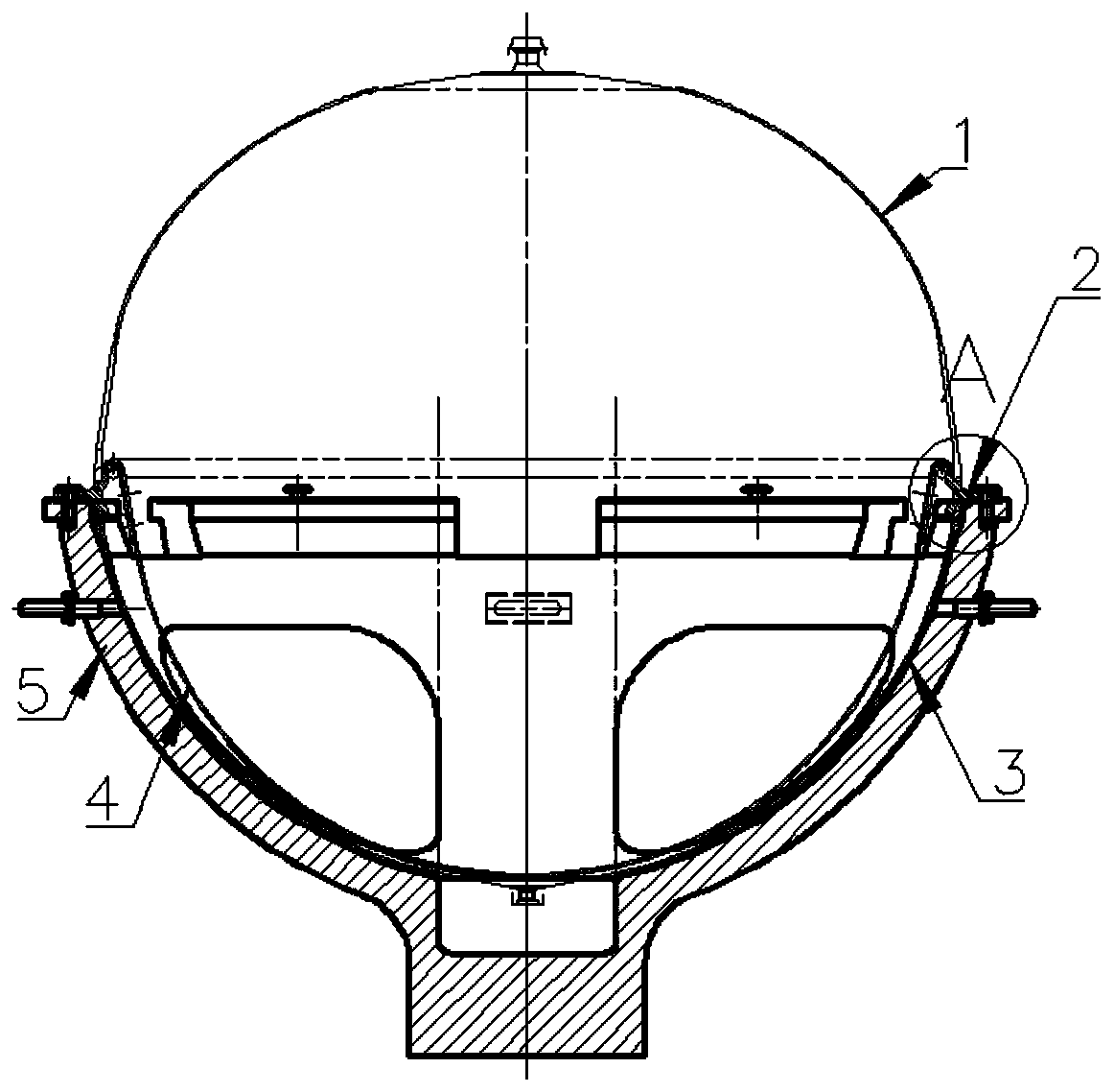
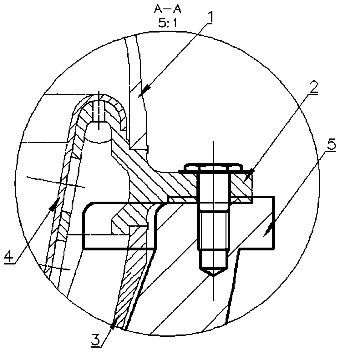
The invention discloses a vacuum electron beam welding method for an aluminum alloy metal diaphragm storage tank. The method comprises the following steps of (1) processing two hemispherical electronbeam welding tools, wherein six notches are uniformly distributed on the hemispherical electron beam welding tools; (2) clamping a support ring, a metal diaphragm and an air cavity shell by utilizinga first electron beam welding tool; (3) firstly, positioning and welding the support ring and the metal diaphragm in a segmented mode, secondly, positioning and welding the support ring and the air cavity shell through the gap of a tool, and finally, welding the support ring and the metal diaphragm through electron beams in the whole circumference; (4) removing the first electron beam welding tool, clamping all the components on the second electron beam welding tool, wherein a liquid cavity shell is located below the second electronic beam welding tool, firstly positioning and welding the support ring and the liquid cavity shell through the gap of the tool at first, and welding the support ring and the air cavity shell by the electron beams in the whole circumference; and (5) removing thesecond electron beam welding tool, clamping the product by using the first electron beam welding tool, and welding the support ring and the liquid cavity shell by using the electron beams in the wholecircumference. Through the method disclosed by the invention, the internal quality qualification rate and the welding line strength of the electron beam welding line of the aluminum alloy metal diaphragm storage tank are improved.

Description

technical field [0001] The invention relates to a vacuum electron beam welding method for an aluminum alloy metal diaphragm storage tank, which belongs to the field of mechanical processing. Background technique [0002] The main problem of the current aluminum alloy electron beam welding is the existence of pores and cracks, and for the single-lock bottom butt joint structure, it is prone to defects of poor fusion at the root, resulting in a decrease in weld strength. At the same time, due to the three electron beams of the aluminum alloy metal diaphragm tank The welds are relatively close to each other, resulting in greater mutual influence between the welds. If the welding sequence is unreasonable, the strength of the weld after welding will decrease, and leakage will occur during the hydraulic test of the tank. Contents of the invention [0003] The technical problem of the present invention is: to overcome the deficiencies in the prior art, and to provide a method for...

Claims


Application Information

Patent Timeline
Patent Type & Authority Applications(China)
IPC IPC(8): B23K15/06B23K37/04B23K101/10
CPCB23K15/0053B23K15/06B23K37/0435B23K2101/10
Inventor 王英杰殷满虎
Owner XIAN SPACE ENGINE CO LTD
Learn More