
Power system for hump gear reducers

A technology of hump reducer and power system, which is applied in the direction of power network operating system integration, emergency power supply arrangement, information technology support system, etc., can solve the problem of hump reducer not working, reduce the scope of fault judgment and avoid out of control Effect

Inactive Publication Date: 2015-04-22
武汉钢铁有限公司
View PDF4 Cites 0 Cited by
  • Summary
  • Abstract
  • Description
  • Claims
  • Application Information

AI Technical Summary

Problems solved by technology

[0005] The embodiment of the present invention solves the technical problem in the prior art that when the AC power fails, all the hump reducers in the system cannot work by providing a hump reducer power supply system

Method used


Image

  • Power system for hump gear reducers
  • Power system for hump gear reducers

Examples


Embodiment Construction

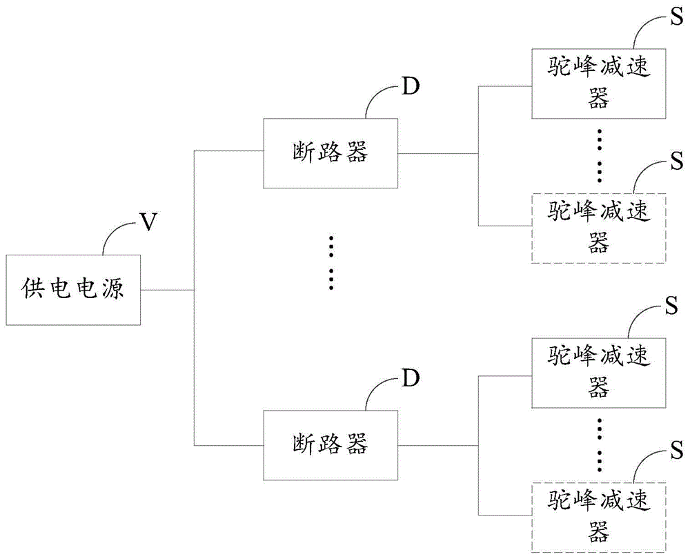
[0025] In order to solve the technical problem in the prior art that all hump reducers in the system cannot work when the AC power fails, the embodiment of the present invention provides a power supply system for hump reducers. After being divided into multiple sub-power supplies, use the multi-channel sub-power supply to supply power to multiple hump reducers. When the sub-power supply fails or fails, only the circuit where the sub-power supply is located is out of control, effectively avoiding the loss of control of the entire hump reducer. At the same time, the scope of fault judgment is also reduced, and hierarchical control can be realized, the peak value can be effectively staggered, and power transmission can be realized step by step.

[0026] In order to make the purpose, technical solutions and advantages of the embodiments of the present invention clearer, the technical solutions in the embodiments of the present invention will be clearly and completely described belo...


PUM


Abstract

The invention relates to the technical field of power design, in particular to a power system for hump gear reducers. The power system for the hump gear reducers comprises a power supply, a plurality of circuit breakers and the hump gear reducers. The power supply is connected with the hump gear reduces through the circuit breakers. The circuit breakers divide the power supply into a plurality of branch power supplies, and the branch power supplies provide power for the hump gear reduces respectively. According to the power system, after the circuit breakers are used for dividing the power supply into the branch power supplies, the branch power supplies are used for supplying power to the hump gear reducers, when power outage or power failure happens to one branch power supply, only a circuit where the branch power supply is placed is out of control, and the hump gear reducers in the full field are effectively prevented from being out of control. Meanwhile, the fault judgment range is also reduced, moreover, hierarchical control can be achieved, peak values are effectively staggered, and power transmission is achieved step by step.

Description

technical field [0001] The invention relates to the technical field of power supply design, in particular to a hump reducer power supply system. Background technique [0002] During the dismantling of the hump, the decoupling vehicle slides to the marshalling line by its own gravity. During this process, the rolling speed of the uncoupling vehicle needs to be controlled and adjusted, otherwise it will cause major accidents such as rear-end collision and sideways collision. The hump reducer is an important device to control and adjust the speed of the slippery vehicle to avoid rear-end collisions and side safety accidents. Taking the TJDY type reducer as an example, the motor is used to drive the oil pump to replenish hydraulic oil to the accumulator. When the vehicle enters the brake rail of the reducer through the guide angle of the two brake rails, the two brake rails are squeezed. As a result, the system pressure rises and reacts to the inner side of the wheel through th...

Claims


Application Information

Patent Timeline
Patent Type & Authority Applications(China)
IPC IPC(8): H02J9/00
CPCY02B70/30Y04S20/20
Inventor 周秀芝蒋秋林陈先祥张海滨李进才李佳状
Owner 武汉钢铁有限公司
Learn More