
Grain structure numerical prediction method in metal rapid prototyping process

A metal rapid prototyping and numerical prediction technology, applied in the direction of process efficiency improvement, energy efficiency improvement, additive manufacturing, etc., can solve problems such as large amount of calculation, achieve optimization of process, huge market application potential, and accurately predict grain structure. Effect

Active Publication Date: 2020-04-21
HARBIN UNIV OF SCI & TECH
View PDF7 Cites 4 Cited by
  • Summary
  • Abstract
  • Description
  • Claims
  • Application Information

AI Technical Summary

Problems solved by technology

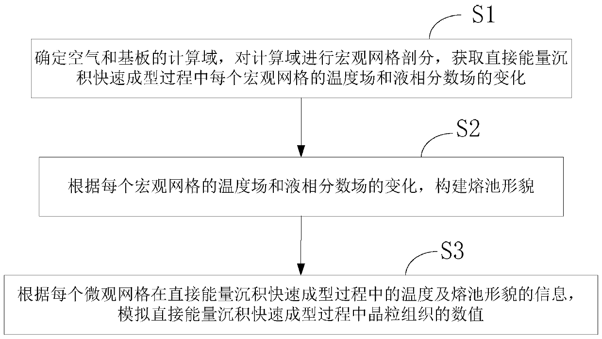
[0006] Aiming at the problem of large amount of calculation in simulating the grain structure in the existing energy deposition rapid prototyping process, the present invention provides a numerical prediction method for the grain structure in the metal rapid prototyping process

Method used


Image

  • Grain structure numerical prediction method in metal rapid prototyping process
  • Grain structure numerical prediction method in metal rapid prototyping process
  • Grain structure numerical prediction method in metal rapid prototyping process

Examples


Embodiment 1

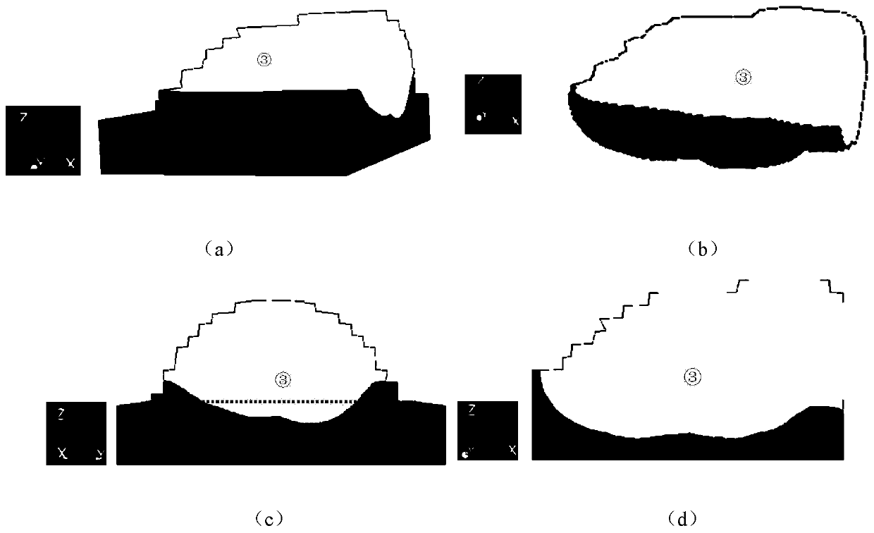
[0283] Example 1: Such as figure 2 As shown, the Z axis is the direction of gravity, and the X axis is the direction of laser migration. The label "①" represents the substrate, the label "③" represents the molten pool, and the label "②" represents the epitaxial crystal grain nucleation area. In the direct energy deposition process, the substrate is heated to melt and then solidifies. The formed molten pool is not rectangular, and the morphology of the molten pool is related to the physical properties of the alloy itself and process parameters. Such as figure 2 As shown in (c), the depth of substrate melting (H e ) Will affect the bonding strength between the melt channel above the substrate and the substrate, H e The larger the bond strength will increase. figure 2 (d) is the central cross section perpendicular to the Y axis. It can be seen that a continuous molten pool is formed in the substrate, thus ensuring the continuity of the structure and the uniformity of mechanical...

Embodiment 2

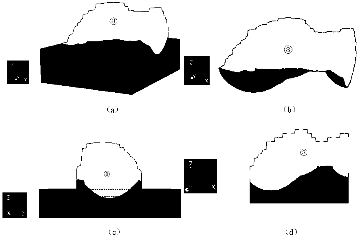
[0286] Example 2: Such as image 3 As shown, the Z axis is the direction of gravity, and the X axis is the direction of laser migration. The label "①" represents the substrate, the label "③" represents the molten pool, and the label "②" represents the epitaxial crystal grain nucleation area. In this embodiment, the viscosity of the liquid is high, and the molten metal basically does not flow. Some existing studies generally assume that the liquid does not flow to simplify calculations. Compared image 3 (c) and figure 2 (c) It can be seen that due to image 3 There is no liquid flowing in it, so the formed molten pool is narrower and the molten channel above the substrate is higher. image 3 (d) is the central section perpendicular to the Y axis, contrast image 3 (d) and figure 2 (d) It can be seen that in image 3 (d) There is a tiny area (wire frame) above the middle substrate, which is formed by metal powder that is not completely melted, which destroys the connectivity be...


PUM


Abstract

The invention discloses a grain structure numerical prediction method in a metal rapid prototyping process, solves a problem of large calculation amount during grain structure simulation in an energydeposition rapid prototyping process in the prior art and belongs to the technical field of rapid metal prototyping. The method comprises steps of S1, determining a computational domain of the air anda substrate, and carrying out macroscopic mesh generation of the computational domain to obtain changes of a temperature field and a liquid phase fraction field of each macroscopic mesh in a direct energy deposition rapid prototyping process; S2, according to the obtained changes of the temperature field and the liquid phase fraction field, dividing each macroscopic grid into a plurality of microcosmic grids, constructing the morphology of a molten pool, specifically, the information of the morphology comprises the number of crystalline grains of the non-molten part of a substrate, whether the microcosmic grids are molten or not in the direct energy deposition rapid prototyping process, epitaxial growth and the number of epitaxial growth cores; and S3, simulating the numerical value of the grain structure in the direct energy deposition rapid prototyping process according to the temperature of each micro grid in the direct energy deposition rapid prototyping process and the information of the morphology of the molten pool.

Description

Technical field [0001] The invention relates to a method for predicting a numerical value of a grain structure in a metal rapid prototyping process, and belongs to the technical field of metal rapid prototyping. Background technique [0002] Metal additive manufacturing is a rapid prototyping technology due to its high cooling rate during solidification. With the rapid development of modern industry and the improvement of design and manufacturing capabilities, the morphology of metal components has become more and more complex (the thickness ratio increases, and the area of ​​irregular curved surfaces increases). Whether metal components can meet the requirements of practical applications to a large extent Depends on its dimensional accuracy, shape accuracy and overall integrity. Traditional casting technology is difficult to ensure the accuracy of various aspects in the preparation of metal components with complex shapes. The main reason is that the casting process requires mol...

Claims


Application Information

Patent Timeline
Patent Type & Authority Applications(China)
IPC IPC(8): B22F3/105B33Y50/00
CPCB33Y50/00B22F10/00B22F10/38B22F10/368B22F10/25Y02P10/25
Inventor 刘东戎赵红晨浦震鹏
Owner HARBIN UNIV OF SCI & TECH
Learn More