Overvoltage and low-voltage sensing automatic gear shifting transformer

A transformer and low-voltage technology, applied in the field of transformer supporting facilities, can solve the problems of low-voltage or over-voltage, inconvenient maintenance and high cost, and achieve the effects of timely action response, convenient maintenance and low cost

Active Publication Date: 2020-04-17
STATE GRID SHANDONG ELECTRIC POWER +1
View PDF5 Cites 2 Cited by
  • Summary
  • Abstract
  • Description
  • Claims
  • Application Information

AI Technical Summary

Problems solved by technology

[0007] 1. In the process of realizing remote automatic control, a large amount of data calculation and transmission are required. In the existing remote network transmission process, it is easily affected by network speed transmission speed, signal strength, data conversion and delay , and in the actual voltage adjustment process, what is needed is quick response, quick action, and a delay of a few seconds is very likely to cause low voltage or overvoltage accidents;
[0008] Collect parameters such as three-phase voltage, three-phase current, three-phase active power, three-phase reactive power, total active power, total reactive power, total apparent power, three-phase power factor and line frequency of the transformer, collect these data and The corresponding sensors are not only costly and inconvenient to maintain, but also all kinds of sensor modules affect each other, and the collected data is centrally transmitted to the controller for processing. Once one of the collected data is broken, delayed or damaged, the control If the device cannot receive or delay this data, it will directly affect all subsequent actions

Method used


Image

  • Overvoltage and low-voltage sensing automatic gear shifting transformer
  • Overvoltage and low-voltage sensing automatic gear shifting transformer
  • Overvoltage and low-voltage sensing automatic gear shifting transformer

Examples


Embodiment Construction

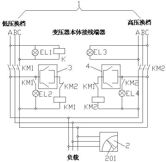
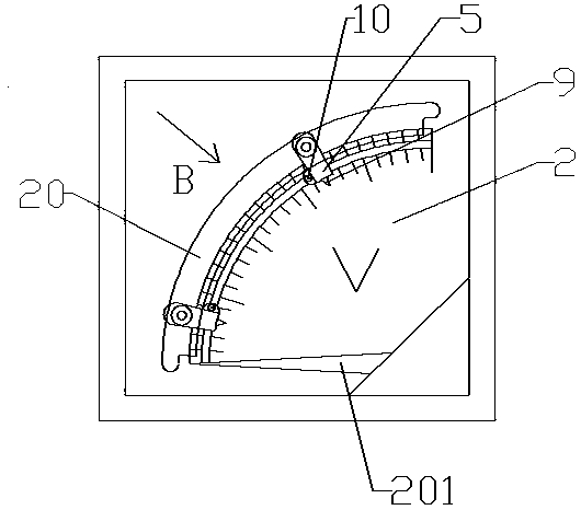
[0030] Accompanying drawing is the specific embodiment of the present invention. like Figures 1 to 5 As shown, the sensed overvoltage and low-voltage automatic shifting transformer includes a transformer body 1 and a voltmeter 2 for detecting the voltage of the transformer body 1. The terminals of the transformer body 1 are electrically connected to the low-voltage shifting module 3 and the high-voltage shifting module 3 respectively. The gear module 4; the low-voltage shift module 3 and the high-voltage shift module 4 form an interlock through the contactor, the contactor is the contactor KM1 and the contactor KM2, and the low-voltage shift module 3 is formed by the normally closed contact between the low-voltage start module and the contactor KM2 The high-voltage shift module 4 is composed of the high-voltage starting module, the normally closed contact of the contactor KM1 and the coil of the contactor KM2 in series; the low-voltage starting module and the high-voltage sta...


PUM


Abstract

The invention relates to the field of transformer supporting facilities, and particularly discloses an overvoltage and low-voltage sensing automatic gear shifting transformer, which comprises a transformer body and a voltmeter for detecting the voltage of the transformer body, and is characterized in that the wiring end of the transformer body is electrically connected with a low-voltage gear shifting module and a high-voltage gear shifting module respectively; the low-voltage gear shifting module is formed by connecting a low-voltage starting module, a normally-closed contact of a contactor KM2 and a coil of a contactor KM1 in series, and the high-voltage gear shifting module is formed by connecting a high-voltage starting module, a normally-closed contact of the contactor KM1 and a coilof the contactor KM2 in series; and the low-voltage starting module and the high-voltage starting module are controlled to be started through swinging of a pointer of the voltmeter. The air low-voltage gear shifting module and the high-voltage gear shifting module are automatically started according to the sweeping times of the low-voltage starting module and the high-voltage starting module, thecontrol precision is high, the action response is timely, the cost is low, and the maintenance is convenient.

Description

technical field [0001] The invention relates to the field of supporting facilities for transformers, in particular to an overvoltage-sensing and low-voltage automatic shifting transformer. Background technique [0002] Transformer is a device that uses the principle of electromagnetic induction to change AC voltage. The main components are primary coil, secondary coil and iron core (magnetic core). The main functions are: voltage conversion, current conversion, impedance conversion, isolation, voltage stabilization (magnetic saturation transformer), etc. According to the purpose, it can be divided into: power transformers and special transformers (circuit transformers, rectifier transformers, power frequency test transformers, voltage regulators, mining transformers, audio transformers, intermediate frequency transformers, high frequency transformers, impact transformers, instrument transformers, electronic transformers , reactors and transformers, etc.). [0003] The over...

Claims


Application Information

Patent Timeline
Patent Type & Authority Applications(China)
IPC IPC(8): H01F29/04H01F27/40G01R31/62G01R19/00
CPCH01F29/04H01F27/402H01F27/40G01R19/0084
Inventor 刘国栋宋来森吴超李培崔德春王会桥白学光王哲张逢雪牛学洲成红星张圣光李泽鹏田运涛商帅
Owner STATE GRID SHANDONG ELECTRIC POWER
Why Eureka
Try Eureka