An automatic pressure regulating device for a station transformer
A technology of automatic voltage regulation and substation transformer, which is applied in the field of power voltage regulation, can solve the problems that cannot meet the needs of power system voltage regulation, and achieve the effects of low power consumption, flexible expansion, and accurate voltage regulation
- Summary
- Abstract
- Description
- Claims
- Application Information
AI Technical Summary
Problems solved by technology
Method used
Image

Examples
Embodiment 1
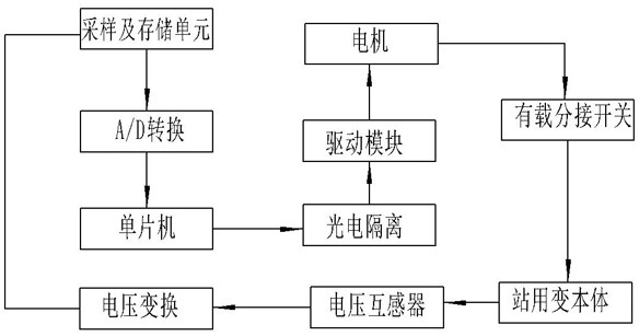
[0025] Such as figure 1 Shown is a schematic structural diagram of a substation automatic voltage regulation device provided in this embodiment, which is suitable for substations. The voltage regulation device includes a sampling and storage unit connected to the station substation for sampling voltage information. The above sampling and storage unit samples the output voltage of the voltage output terminal of the substation transformer body through the sampling circuit, and transmits the information to the processing unit, and the processing unit transmits the information to the control unit, and the control unit compares the received information with the set voltage reference When the output voltage is not within the range of the voltage reference value, the control unit controls the drive module of the on-load tap-changer to drive the motor to perform forward and reverse motions to realize the lifting and lowering of the switch gear.
[0026] The processing unit includes A / ...
Embodiment 2
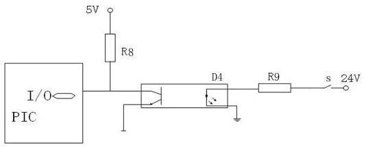
[0032] The difference from the embodiment is that the switch position detection circuit in the voltage regulating device provided by this embodiment includes a photosensitive transistor and a light emitting diode D4, such as image 3 As shown, the phototransistor is coupled with the light-emitting diode D4, the positive input terminal of the phototransistor is connected with the PIC microcontroller, the positive input terminal of the phototransistor is connected with the resistor R8, and the resistor R8 is connected with the 5V power supply. The negative input terminal of the phototransistor is grounded, the anode of the light emitting diode D4 is connected to one end of the resistor R9, the other end of the resistor R9 is connected to the 24V power supply through the switch S, and the cathode of the light emitting diode D4 is grounded. If the light-emitting diode D4 has a signal input, it outputs a luminous flux proportional to the magnitude of the current, and the phototransi...
Embodiment 3
[0034] The difference between this embodiment and Embodiment 1 is that the drive circuit in the voltage regulating device provided by this embodiment includes a resistor R10 and a resistor R11 respectively connected to the PIC microcontroller, such as Figure 4 As shown, the other end of the resistor R10 is connected to the base of the triode VT1, the emitter of the triode VT1 is grounded, the collector of the triode VT1 is connected to the relay K2, and the other end of the relay K2 is connected to the positive 6V Power supply, the two ends of the relay K2 are connected in parallel with a diode D5, the cathode of the diode D5 is connected to the positive 6V power supply; the other end of the resistor R11 is connected to the base of the triode VT2, and the emitter of the triode VT2 Grounded, the collector of the triode VT2 is connected to the relay K1, the other end of the relay K1 is connected to a positive 6V power supply, the two ends of the relay K1 are connected in paralle...
PUM
 Abstract
Description
Claims
Application Information
 - R&D
- Intellectual Property
- Life Sciences
- Materials
- Tech Scout
- Unparalleled Data Quality
- Higher Quality Content
- 60% Fewer Hallucinations
Browse by: Latest US Patents, China's latest patents, Technical Efficacy Thesaurus, Application Domain, Technology Topic, Popular Technical Reports.
© 2025 PatSnap. All rights reserved.Legal|Privacy policy|Modern Slavery Act Transparency Statement|Sitemap|About US| Contact US: help@patsnap.com