Long-range surface shape detector and detection method

A long-range surface and detector technology, applied in instruments, measuring devices, optical devices, etc., can solve problems such as many errors, uneven processing of pixel points of area array detectors, inconsistent photoelectric response efficiency, and electronic circuit consistency. , to achieve the effect of reducing system errors and overcoming them

Active Publication Date: 2020-04-17
合肥名龙电子科技有限公司
View PDF12 Cites 3 Cited by
  • Summary
  • Abstract
  • Description
  • Claims
  • Application Information

AI Technical Summary

Problems solved by technology

[0009] As can be seen above, in the existing long-distance surface shape measurement technical solutions, the purpose of reducing optical elements and reducing optical elements that introduce errors is achieved through structural changes, and the systematic error has not been completely or better eliminated, and through The difference between the landing points of the measuring spot on the area array detector (CCD) of the f-θ angle detection system is used to feed back the surface shape of the optical device under test, and there are also area array detectors inevitably. The processing inhomogeneity of pixels, the inconsistency of photoelectric response efficiency, and the consistency of electronic circuits, etc., lead to system errors. In theory, the greater the distance between the Fourier transform lens and the area array detector, the higher the resolution , in the current detection form, the larger the distance, the more errors will be introduced at different points on the area array detector (CCD), which is contradictory

Method used


Image

  • Long-range surface shape detector and detection method
  • Long-range surface shape detector and detection method
  • Long-range surface shape detector and detection method

Examples


Embodiment Construction

[0029] The specific implementation manners of the present invention will be further described in detail below in conjunction with the accompanying drawings.

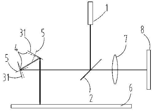
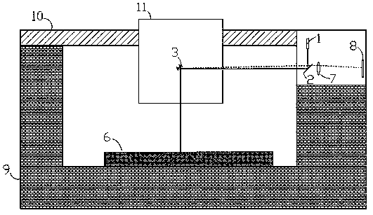
[0030] See figure 1 , figure 2, the long-range surface shape detector of the specific embodiment is used to carry out surface shape detection on the surface of the optical device 6 to be tested. The long-range surface shape detector includes a light source 1, a beam splitter 2, and a double reflection surface 4 constituting a pentaprism-like structure The double-mirror unit 3 and the f-θ angle detection system, the f-θ angle detection system includes a Fourier transform lens 7 and an array detector 8; the outgoing light beam provided by the light source 1 is reflected to the described beam splitter 2 The double-mirror unit 3 is then reflected to the surface of the optical device 6 to be tested by the double-mirror unit 3, reflected by the surface of the optical device 6 to be tested, and then reflected to the beam spli...


PUM

PropertyMeasurementUnit
diameteraaaaaaaaaa

Abstract

The invention relates to a long-range surface shape detector and a detection method. The detector comprises a light source, a beam splitter, a double-mirror unit, a Fourier transform lens and an areaarray detector, wherein the double-mirror unit forms an equivalent pentaprism. A light beam emitted by the light source passes through the beam splitter and the double-mirror unit to reach the surfaceof a to-be-detected optical device, is reflected and then passes through the double-mirror unit, the beam splitter and the Fourier transform lens to reach the area array detector, and a measurement light spot is formed. The double-mirror unit comprises two plane mirrors. The two plane mirrors can independently rotate along respective rotating shafts respectively. The two rotating shafts are positioned on the same plane and form an included angle of 45 degrees. The plane mirrors and the rotating shafts are obliquely crossed, and the angle formed by the plane mirrors and the rotating shafts isset according to the measurement range requirement, so that the angle of an emergent light path after reflection by the double-mirror unit is changed through rotation, and the emergent light path is incident to the surface of the to-be-detected optical device in a normal incidence form. The surface shape of the to-be-detected optical device can be obtained through the rotation amounts of the two plane mirrors. Therefore, the detection precision is improved.

Description

technical field [0001] The invention belongs to the technical field of long-range mirror surface shape detection, and in particular relates to a long-range surface shape detector and a detection method. Background technique [0002] With the continuous development of science and technology, various application fields have put forward higher requirements for the detection of mirror surface shape. In order to improve the detection capability of the long-range surface profiler, it is necessary to correct or eliminate various system errors. Among these system errors, the most important type is introduced due to the slight difference between the optical elements used in the optical path system of the long-range surface profiler and the ideal optical elements, which are mainly manifested in two aspects: [0003] On the one hand, the small processing difference between the surface shape of each reflective optical element in the optical path system and the surface shape of the idea...

Claims


Application Information

Patent Timeline
Patent Type & Authority Applications(China)
IPC IPC(8): G01B11/25
CPCG01B11/25
Inventor 彭川黔龚恒翔
Owner 合肥名龙电子科技有限公司
Why Eureka
Try Eureka