Long-range optical surface profile detection device and detection method

A detection device and surface technology, applied in the direction of optical devices, measuring devices, instruments, etc., can solve the problems of many errors, uneven processing of pixel points of area array detectors, inconsistent photoelectric response efficiency, and consistency of electronic circuits. Achieve the effects of avoiding angle errors, overcoming system errors, and improving detection accuracy

Active Publication Date: 2021-07-27
CHONGQING UNIV OF TECH
View PDF13 Cites 1 Cited by
  • Summary
  • Abstract
  • Description
  • Claims
  • Application Information

AI Technical Summary

Problems solved by technology

[0009] As can be seen above, in the existing long-distance surface shape measurement technical solutions, the purpose of reducing optical elements and reducing optical elements that introduce errors is achieved through structural changes, and the systematic error has not been completely or better eliminated, and through The difference between the landing points of the measuring spot on the area array detector (CCD) of the f-θ angle detection system is used to feed back the surface shape of the optical device under test, and there are also area array detectors inevitably. The processing inhomogeneity of pixels, the inconsistency of photoelectric response efficiency, and the consistency of electronic circuits, etc., lead to system errors. In theory, the greater the distance between the Fourier transform lens and the area array detector, the higher the resolution , in the current detection form, the larger the distance, the more errors will be introduced at different points on the area array detector (CCD), which is contradictory

Method used


Image

  • Long-range optical surface profile detection device and detection method
  • Long-range optical surface profile detection device and detection method
  • Long-range optical surface profile detection device and detection method

Examples


Embodiment Construction

[0049] The specific implementation manners of the present invention will be further described in detail below in conjunction with the accompanying drawings.

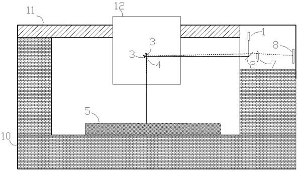
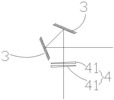
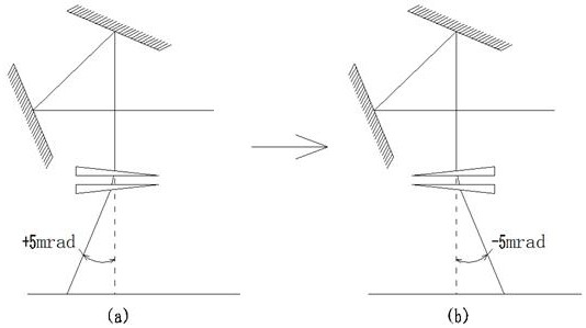
[0050] See figure 1 , figure 2 , the long-distance optical surface shape detection device of the specific embodiment is used for surface shape detection of the surface of the optical device 5 to be tested, including a detection optical path and an f-θ angle detection system for forming a measurement spot, and in the detection optical path, A double wedge mechanism 4 is provided on the incident light path directly incident on the surface of the optical device to be tested, and the double wedge mechanism 4 includes two single wedge-shaped wedges 41 arranged at intervals along the incident light path. Through two single-body wedge-shaped wedges 41, the two single-body wedge-shaped wedges 41 can be rotated independently to change the angle of the outgoing light path through rotation and make the outgoing light path inciden...


PUM


Abstract

The invention relates to a long-range optical surface shape detection device and detection method. The surface shape detection device includes a detection optical path and an f-θ angle detection system for forming a measurement spot. A double wedge mechanism is provided on the incident light path, and the double wedge mechanism includes two single wedge wedges arranged at intervals along the incident light path, the incident light path passes through the two single wedge wedges, and the two single wedge wedges It can be rotated independently to change the angle of its outgoing light path and make the outgoing light path incident on the surface of the optical device to be tested in the form of normal incidence. In the present invention, by rotating the wedge, the reflected light path returns along the original path of the incident light path and can be judged in conjunction with the measurement spot. The surface shape of the optical device to be tested is obtained by the rotation of the wedge, and the position of the light path on each optical element is consistent. The angle error of each optical element introduced by the lateral displacement in the traditional system can be completely avoided, and the detection accuracy can be improved.

Description

technical field [0001] The invention belongs to the technical field of surface shape detection of long-range mirrors, and in particular relates to a long-range optical surface shape detection device and detection method. Background technique [0002] With the continuous development of science and technology, various application fields have put forward higher requirements for the detection of mirror surface shape. In order to improve the detection capability of the long-range surface profiler, it is necessary to correct or eliminate various system errors. Among these system errors, the most important type is introduced due to the slight difference between the optical elements used in the optical path system of the long-range surface profiler and the ideal optical elements, which are mainly manifested in two aspects: [0003] On the one hand, the small processing difference between the surface shape of each reflective optical element in the optical path system and the surface...

Claims


Application Information

Patent Timeline
Patent Type & Authority Patents(China)
IPC IPC(8): G01B11/24
CPCG01B11/24
Inventor 彭川黔
Owner CHONGQING UNIV OF TECH
Why Eureka
Try Eureka