
Split self-propelled construction method adopted in large-span subway tunnel second-liner arch apex

A construction method and large-span technology, applied in the direction of tunnel lining, tunnel, shaft lining, etc., can solve problems such as high construction cost, poor construction environment, and limited distance, and achieve control of deformation and surface settlement, improvement of construction efficiency, and control The effect of tunnel deformation

Active Publication Date: 2020-04-17
CCCC SECOND HARBOR ENG
View PDF4 Cites 4 Cited by
  • Summary
  • Abstract
  • Description
  • Claims
  • Application Information

AI Technical Summary

Problems solved by technology

The disadvantages of the existing conventional lining technology include: 1) The temporary support of the initial support structure is used as a whole, which is risky; 2) In order to prevent major hazards such as tunnel deformation caused by the removal of the temporary support, the distance of the construction section is limited, which cannot meet the requirements of the tunnel lining. The process flow operation is required, and the efficiency is low; the overall lining of the trolley is used, and the construction cost is high; 3) the overall support is broken, and the workload is heavy, resulting in a poor construction environment in the tunnel; The binding operation is difficult and the efficiency is low; 5) Repeatedly building and dismantling the lining system takes a lot of time and the cycle is long; 6) High-altitude operations are risky

Method used


Image

  • Split self-propelled construction method adopted in large-span subway tunnel second-liner arch apex
  • Split self-propelled construction method adopted in large-span subway tunnel second-liner arch apex
  • Split self-propelled construction method adopted in large-span subway tunnel second-liner arch apex

Examples


Embodiment 1

[0059] This embodiment is applied to the two-lining and three-step construction technology of Harbin Metro TJ-12 standard large-span high-risk shallow-buried tunnel. This embodiment overcomes the structural deformation caused by the construction of the secondary lining of the high-risk large-span underground excavation tunnel under complex geological conditions, causing risks such as surface settlement and tunnel instability. The compactness of the secondary lining structure of the tunnel is improved, and the thickness of the reinforced protective layer and the thickness of the main structure of the secondary lining are better controlled.

[0060] The invention provides a split self-propelled construction method for the second lining vault of a large-span subway tunnel, including:

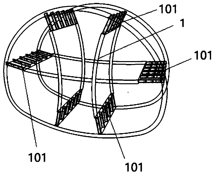
[0061] Step 1, such as figure 1 As shown, before the construction, the concrete 101 at the joint between the temporary support 1 and the primary support structure 3 is first removed. In this embod...


PUM


Abstract

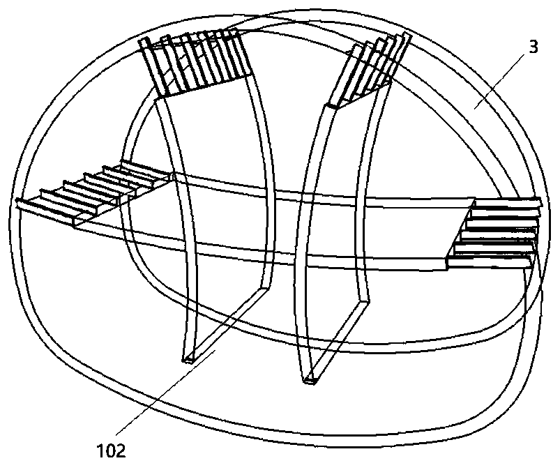
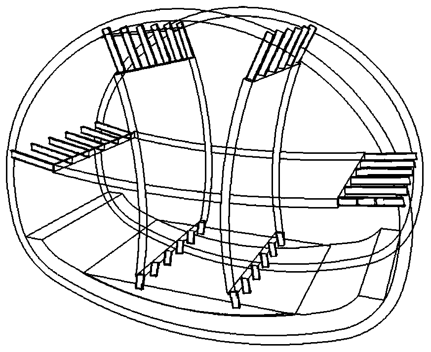
The invention discloses a self-propelled model board trolley construction method adopted in a large-span subway tunnel second-liner arch apex. Before double-side-wall pioneer drift method secondary lining construction, concrete at the joint of a temporary support and a primary-support structure is removed at first, and the three-step approach of inverted arch heading, side wall following and archapex closing is adopted in secondary lining construction. According to inverted arch heading, median septum H-steel at the bottom of the inside of an inverted arch construction section is locally dismantled during inverted arch construction, and then the inverted arch construction is conducted. According to side wall following, a horizontal part medium partition plate inside a side wall construction section is locally dismantled when a side wall within the inverted arch range is constructed. According to arch apex closing, an arch apex within the side wall range is constructed. By adoption ofthe self-propelled model board trolley construction method adopted in the large-span subway tunnel second-liner arch apex, the risks like structural distortion, ground surface settlement and tunnel unstability caused by high-risk large-span subsurface tunnel secondary lining construction under complicated geological conditions are eliminated.

Description

technical field [0001] The invention relates to the field of tunnel construction. More specifically, the invention relates to a separate self-propelled construction method for the second lining vault of a large-span subway tunnel. Background technique [0002] In urban rail transit, railways, highways, underground caverns and other underground engineering long-span tunnel constructions, for sections with poor surrounding rock grades and complex geological conditions, the double-side pilot pit method, The CRD method and other construction methods with temporary support structures such as temporary inverted arches and temporary partition walls are used for construction to control the deformation of the primary support structure. In traditional construction, before the construction of the secondary lining, it is necessary to carry out trial demolition of temporary supports one by one, and at the same time intensively observe the deformation of the primary support structure. H...

Claims


Application Information

Patent Timeline
Patent Type & Authority Applications(China)
IPC IPC(8): E21D11/10E21D11/38
CPCE21D11/105E21D11/102E21D11/107E21D11/38
Inventor 常东辉李金州张静袁青周彦军范小培李成梅
Owner CCCC SECOND HARBOR ENG
Learn More