Power supply control system and power supply control method for locomotive

A technology for power supply control and locomotives, which is applied to electrical devices, electric vehicles, vehicle components, etc., and can solve problems such as adverse effects of locomotive equipment and power grid equipment.

Active Publication Date: 2021-05-11
ZHUZHOU ELECTRIC LOCOMOTIVE CO LTD
View PDF11 Cites 0 Cited by
  • Summary
  • Abstract
  • Description
  • Claims
  • Application Information

AI Technical Summary

Problems solved by technology

[0004] In view of this, the purpose of this application is to provide a locomotive power supply control system and power supply control method to solve the problem of adverse effects on locomotive equipment and power grid equipment when the locomotive runs through the non-electric zone

Method used


Image

  • Power supply control system and power supply control method for locomotive
  • Power supply control system and power supply control method for locomotive
  • Power supply control system and power supply control method for locomotive

Examples


Embodiment Construction

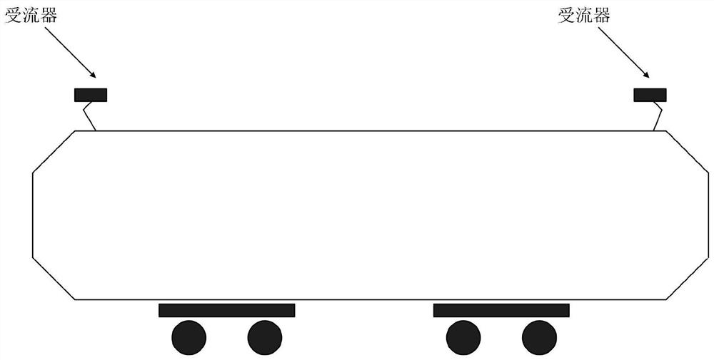
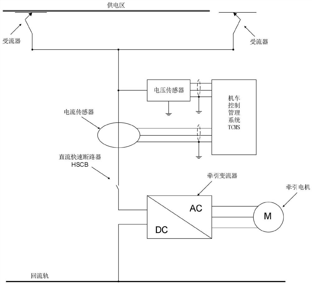
[0041]figure 2 A schematic diagram of the mounting position of the locomotive. In the prior art, only one transducer is used when the locomotive is running, such asimage 3 Showimage 3 Structure of power supply control system for existing locomotives.

[0042]Applicants have found that when the locomotive's flowers enter the universal zone, the TCMS (locomotive control management system) can detect the grid undervoltage signal and current zero signal, thereby determining the locomotive into the powerless zone. Since the locomotive uses only one transformer, and TCMS cannot pre-proportioner locomotive will enter the powerless zone, the locomotive cannot actively uninstall in the moment of entering the powerless zone, causing the locomotive to enter the powerless zone, easy to generate a bow network arrangement , Adverse effects on locomotive equipment and grid equipment.

[0043]In addition, the locomotive cannot actively uninstall in front of the entering the powerless zone. When the locom...


PUM


Abstract

This application discloses a power supply control system and power supply control method for a locomotive. During the operation of the locomotive, the electric energy is obtained from the catenary through two current receivers, and according to the current value flowing through the two current receivers and the input of the intermediate circuit side voltage value to determine whether the front end of the locomotive enters the dead zone. When it is determined that the front end of the locomotive enters the dead zone, the rear receiver of the locomotive has not yet entered the dead zone, and the locomotive can still obtain power from the catenary. At this time Controlling the unloading of the converter can reduce the possibility of pantograph-catenary arcing when the rear-end current receiver of the locomotive enters the non-electric zone, and even avoid pantograph-catenary arcing, thereby reducing the impact on the locomotive equipment and the power grid. adverse effects of the device.

Description

Technical field[0001]The present application relates to the field of locomotive control technology, and therefore specifically involves a power supply control system and power supply control method of locomotive.Background technique[0002]When the locomotive is running during operation, electrical energy is obtained from the contact network (also known as the electrical bow) to drive the traction motor. There is a certain partition between different supply regions (such asfigure 1 As shown), the area is an electrical region. When the locomotive passes the powerless displacement, the locomotive cannot obtain electric energy from the contact network.[0003]Applicants have found that when the locomotive enters the powerless zone from the electric vehicle, the probability of the bow is high, which will adversely affect the locomotive equipment and grid equipment. In addition, when the locomotive enters an electric region from the powerless zone, the locomotive will produce a large impact ...

Claims


Application Information

Patent Timeline
Patent Type & Authority Patents(China)
IPC IPC(8): B60L9/00B60L3/00
CPCB60L3/00B60L9/00
Inventor 陈安俊李顺袁顺付金胡亮贺琳秦庆民
Owner ZHUZHOU ELECTRIC LOCOMOTIVE CO LTD
Why Eureka
Try Eureka