Eureka AIR delivers breakthrough ideas for toughest innovation challenges, trusted by R&D personnel around the world.

Burr cleaning device with grinding structure for bearing machining

A bearing processing and cleaning equipment technology, applied in the field of bearing processing, can solve the problems of excessive dust content in the workshop, reduce the processing effect, and high difficulty in inserting the outer ring of the bearing, and achieve the effect of reducing load damage and reducing diameter

Inactive Publication Date: 2020-04-17
东莞市史雷帝三维数控科技有限公司
View PDF0 Cites 1 Cited by
  • Summary
  • Abstract
  • Description
  • Claims
  • Application Information

AI Technical Summary

Problems solved by technology

[0004] The purpose of the present invention is to provide a kind of burr cleaning equipment with a grinding structure for bearing processing, so as to solve the problem that the existing burr cleaning equipment proposed in the above background technology is difficult to insert the outer ring of the bearing during use, resulting in a reduction in the processing effect. There is no good dust absorption equipment in use, resulting in the problem that the dust content in the workshop exceeds the standard during use

Method used


Image

  • Burr cleaning device with grinding structure for bearing machining
  • Burr cleaning device with grinding structure for bearing machining
  • Burr cleaning device with grinding structure for bearing machining

Examples


Embodiment Construction

[0026] The technical solutions in the embodiments of the present invention will be clearly and completely described below in conjunction with the accompanying drawings in the embodiments of the present invention. Obviously, the described embodiments are only some of the embodiments of the present invention, not all of them. Based on The embodiments of the present invention and all other embodiments obtained by persons of ordinary skill in the art without making creative efforts belong to the protection scope of the present invention.

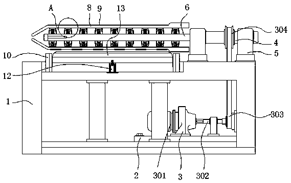
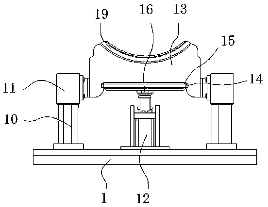
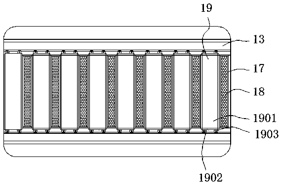
[0027] see Figure 1-5 , the present invention provides a technical solution: a burr cleaning device with a grinding structure for bearing processing, including a body 1, a base 2, a transmission structure 3, a motor 301, a connecting shaft 302, a connecting belt 303, a pulley 304, and a fixed shaft 4 , shaft seat 5, drive shaft 6, connection structure 7, lower frame 701, upper frame 702, compression spring 703, outer splint 8, cushion cover 9, ...


PUM


Abstract

The invention relates to a burr cleaning device with a grinding structure for bearing machining. The burr cleaning device comprises a machine body and a fixing shaft, wherein a base is distributed atthe bottom of the lower end of the machine body; a transmission structure is distributed in the middle of the inner side of the base; the fixing shaft is connected to the tail end of the transmissionstructure; shaft seats are welded to two sides of the outer wall of the fixing shaft; a transmission shaft is distributed in the middle of the inner side of the fixing shaft; connecting structures aredistributed on two sides of the outer wall of the transmission shaft; outer clamping plates are distributed at the tail ends of the connecting structures; soft cushion sleeves are attached to the outer walls of the outer clamping plates; and sliding rails are welded to two sides of the middle of the upper end of the machine body. According to the burr cleaning device, the transmission structure,a motor, a connecting shaft, a connecting belt and a belt wheel are arranged, when a user needs to rotate the fixing shaft, the user can start the motor, the motor drives the connecting shaft to rotate, the connecting belt drives the belt wheel to rotate, the transmission mode adopts a flexible transmission mode, and the transmission effect of the burr cleaning device reduces the possibility of load damage of the motor.

Description

technical field [0001] The invention relates to the technical field of bearing processing, in particular to a burr cleaning device with a grinding structure for bearing processing. Background technique [0002] Bearing is an important part of contemporary mechanical equipment. Its main function is to support the mechanical rotating body, reduce the friction coefficient during its movement, and ensure its rotation accuracy. The grinding accuracy of the outer ring of the bearing directly affects the actual use of the bearing. As a result, the grinding of the outer ring of the bearing is particularly important in the entire bearing processing process. It is necessary to rub the burrs of the outer ring of the bearing to ensure that the outer ring of the bearing can be effectively used as a connecting part. [0003] The existing burr cleaning equipment is difficult to insert the outer ring of the bearing during use, which reduces the processing effect, and there is no good dust a...

Claims


Application Information

Patent Timeline
Patent Type & Authority Applications(China)
IPC IPC(8): B24B9/00B24B55/06B24B41/06B24B47/12B24B41/02B24B45/00
CPCB24B9/005B24B41/02B24B41/067B24B45/006B24B47/12B24B55/06
Inventor 黄红梅孙锦民石宏
Owner 东莞市史雷帝三维数控科技有限公司
Why Eureka
Eureka Blog
Learn More