Vertical feeding welding device

A welding device and feeding technology, applied in welding equipment, laser welding equipment, metal processing equipment, etc., can solve the problem of low welding efficiency, achieve the effect of improving welding efficiency and optimizing welding process

Pending Publication Date: 2020-04-17
DONGGUAN SHENGXIANG PRECISION METAL
View PDF0 Cites 0 Cited by
  • Summary
  • Abstract
  • Description
  • Claims
  • Application Information

AI Technical Summary

Problems solved by technology

[0003] The object of the present invention is to provide a vertical feeding welding device, the jig is provided with a first feeding channel and a second feeding channel perpendicular to each other, and the laser welding head shoots the laser beam laterally to the welding point, so as to realize the welding of multiple workpieces. Welding, improve welding efficiency, solve the problem of low welding efficiency

Method used


Image

  • Vertical feeding welding device
  • Vertical feeding welding device
  • Vertical feeding welding device

Examples


Embodiment Construction

[0035] The present invention will be described in further detail below in conjunction with the accompanying drawings.

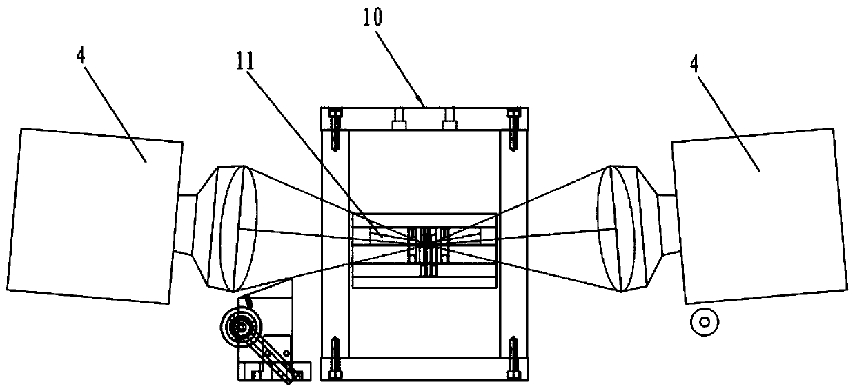
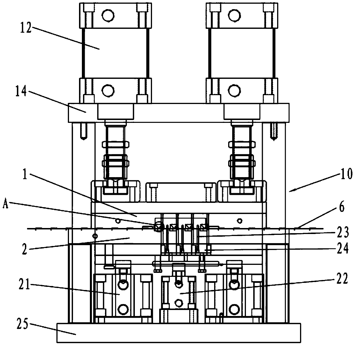
[0036] refer to Figure 1 to Figure 4 , a vertical feeding welding device, including a jig 10 and a laser welding head 4, the jig 10 includes an upper jig 1 and a lower jig 2, and the upper jig 1 can move relative to the lower jig 2;

[0037] The laser welding head 4 is arranged on one side of the jig 10, and can shoot the laser to the welding hole 11 laterally;

[0038] The jig 10 is provided with a first feeding channel 20 and a second feeding channel 30 perpendicular to each other.

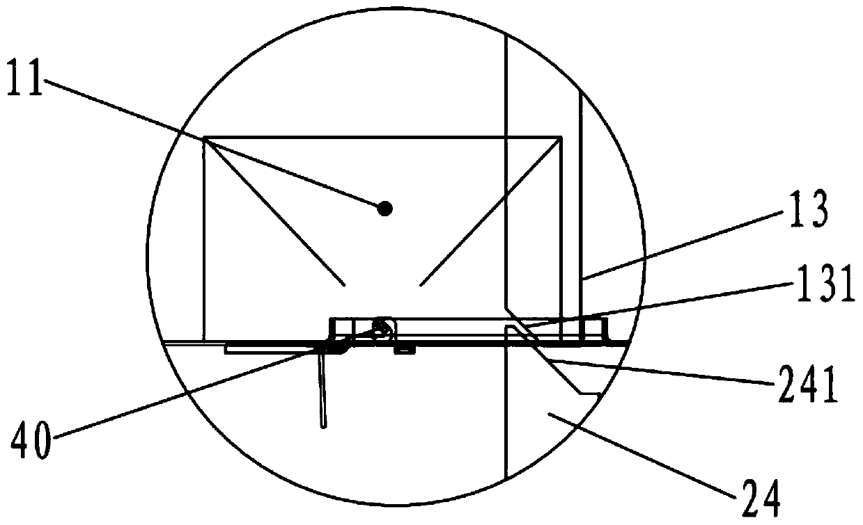
[0039] To further illustrate, the welding hole 11 is provided on the side of the first feeding channel 20 .

[0040] To further illustrate, the lower jig 2 is provided with a positioning pin 23 , a top plate 24 and a positioning cylinder 22 , the output end of the positioning cylinder 22 is drivingly connected to the top plate 24 , and the top plate 24 is connected to the po...


PUM


Abstract

The invention discloses a vertical feeding welding device. The device comprises a jig and a laser welding head, wherein the jig comprises an upper jig body and a lower jig body, and the upper jig bodycan move relative to the lower jig body. The laser welding head is arranged on one side of the jig and can emit laser to a welding hole in the side direction, the jig is provided with a first feedingchannel and a second feeding channel which are perpendicular to each other, two workpieces can be perpendicularly fed, welding spots on a vertical plane are easy to weld, and welding efficiency is improved.

Description

technical field [0001] The invention relates to the technical field of welding machinery, in particular to a vertical feeding welding device. Background technique [0002] The essence of laser welding is welding based on the pinhole effect. In order to produce a small hole, a laser beam with a high energy density is required, and the depth of the small hole produced is the welding penetration. As the beam moves across the surface of the workpiece, the hole remains stable and moves through the workpiece, surrounded by a molten pool of liquid. The small hole is filled with metal vapor with a certain pressure, and the metal vapor with a certain pressure is erupted to the surface of the workpiece to complete the welding. For the welding of workpieces with solder joints on the vertical plane, it is necessary to fix the jig and turn it over before welding, and the welding efficiency is low. Contents of the invention [0003] The object of the present invention is to provide a...

Claims


Application Information

Patent Timeline
Patent Type & Authority Applications(China)
IPC IPC(8): B23K26/21B23K26/70B23K26/02
CPCB23K26/02B23K26/21B23K26/702
Inventor 邱有祥谢金
Owner DONGGUAN SHENGXIANG PRECISION METAL
Why Eureka
Try Eureka