Hydraulic telescopic cutter and differential mechanism shell machining method applying the same

A differential housing and hydraulic technology, applied in metal processing equipment, metal processing machinery parts, manufacturing tools, etc., can solve problems such as high requirements, high price, and difficult processing, so as to reduce position accuracy deviation and reduce investment Cost, the effect of reducing investment risk

Inactive Publication Date: 2020-04-17
山东沪金精工科技股份有限公司
View PDF4 Cites 0 Cited by
  • Summary
  • Abstract
  • Description
  • Claims
  • Application Information

AI Technical Summary

Problems solved by technology

[0002] The differential housing is one of the key components in the automobile drive axle assembly. Its processing quality directly affects the meshing accuracy of the final drive gear and the noise index of the drive axle assembly, especially the differential housing, one of the main components. The processing of the inner spherical surface of the housing is relatively difficult and requires high requirements. At present, there are mainly the following methods for processing the inner spherical surface of the differential housing; The machined hole is inserted into the tool holder from both sides to withstand the countersinking tool, and the workpiece moves with the fixture to process the inner spherical surface. The main disadvantages of using countersinking tool are: the shape of the tool is complicated, special order is required, the service life is low, and the price is high
2. It is processed by multi-axis CNC lathe. The tool holder of multi-axis CNC machine tool can do complex plane movement. Through the processed hole, the tool is inserted into the differential shell, and the inner spherical surface is processed. Multi-axis CNC lathe The main features of processing the inner spherical surface: good processing quality and high efficiency, but need to buy imported machine tools, which are expensive
3. Using the swinging tool processing method, a special machine tool is required. During processing, the workpiece rotates and rotates, and the tool bar equipped with the tool enters the differential housing through the machined hole. After being in place, it passes through the connecting rod mechanism in the tool bar. , push the tool out of the tool holder, and make an arc movement around the center of the circle to process the inner spherical surface. When using the swing tool method to process the inner and spherical surfaces, the center of the tool’s arc movement must coincide with the center of the SR51 sphere. The dimensional accuracy depends on the tool The distance from the tip to the center of rotation of the tool cannot compensate for the wear of the tool tip

Method used


Image

  • Hydraulic telescopic cutter and differential mechanism shell machining method applying the same
  • Hydraulic telescopic cutter and differential mechanism shell machining method applying the same
  • Hydraulic telescopic cutter and differential mechanism shell machining method applying the same

Examples


Embodiment Construction

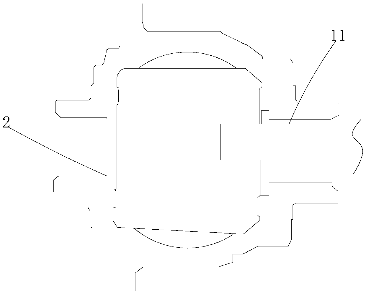
[0021] Such as Figure 1-3 As shown, the present invention provides a technical solution: a hydraulic retractable tool, including a turret 1, a differential case 2, a hinge shaft 3, a connecting rod 4, a tool bar 6, a fixed sleeve 7, a working chamber 8, The end face automatic knife 11, the tool telescopic control connecting rod 12, the tool telescopic hydraulic cylinder 13, the gasket 14 and the ball cage knife 15, the inner wall of the turret 1 is fixedly connected with the outer wall of the working chamber 8, and the outer wall of the fixed sleeve 7 is connected with the working chamber 8 The outer wall of the tool telescopic hydraulic cylinder 13 is fixedly connected to the right side of the tool telescopic control connecting rod 12, the outer surface of the tool telescopic control connecting rod 12 is flexibly connected to the inner wall of the gasket 14, and the tool telescopic control connecting rod The left side of 12 is fixedly connected with the right side of knife b...


PUM


Abstract

The invention relates to the technical field of machining and discloses a hydraulic telescopic cutter. The tool comprises a tool turret, a differential mechanism shell, a hinge shaft, a connecting rod, a cutter bar, a fixing sleeve, a working cavity, an end face automatic tool, a tool telescopic control connecting rod, a tool telescopic hydraulic cylinder, a gasket and a ball cage tool, wherein aninner wall of the tool turret is connected with an outer wall of the working cavity, an outer wall of the fixing sleeve is connected with an outer wall of the working cavity, an output end of the cutter telescopic hydraulic cylinder is connected with a right side surface of the cutter telescopic control connecting rod, an outer surface of the cutter telescopic control connecting rod is connectedwith an inner wall of the gasket, a left side face of the cutter telescopic control connecting rod is connected with a right side face of the cutter bar, an outer surface of the cutter bar is connected with an inner wall of the fixing sleeve, a head of the cutter bar is connected with an outer surface of the hinge shaft, and the end, away from the cutter bar, of the hinge shaft is connected with the end face automatic cutter. The cutter solves problems that machining difficulty of an inner spherical surface of the differential mechanism shell is large, the requirement is high, and machining cost of the inner spherical surface of the differential mechanism shell is high.

Description

technical field [0001] The invention relates to the technical field of mechanical processing, and relates to a hydraulic retractable cutter, in particular to a hydraulic retractable cutter and a differential case processing method using the cutter. Background technique [0002] The differential housing is one of the key components in the automobile drive axle assembly. Its processing quality directly affects the meshing accuracy of the final drive gear and the noise index of the drive axle assembly, especially the differential housing, one of the main components. The processing of the inner spherical surface of the housing is relatively difficult and requires high requirements. At present, there are mainly the following methods for processing the inner spherical surface of the differential housing; The machined hole is inserted into the tool holder from both sides to withstand the countersinking tool, and the workpiece moves with the fixture to process the inner spherical su...

Claims


Application Information

Patent Timeline
IPC IPC(8): B23D79/00B23Q3/00B23Q11/08B23Q5/26
CPCB23D79/00B23Q3/00B23Q5/26B23Q11/08
Inventor 赵文松娄焕军魏胜永吕艳云罗奎郭宜涛
Owner 山东沪金精工科技股份有限公司
Why Eureka
Try Eureka