
An automatic heat treatment equipment for automobile brake pads

A technology for heat treatment equipment and brake pads, applied in heat treatment equipment, heat treatment furnaces, furnaces, etc., can solve problems such as a large amount of manpower, uneven heating, time-consuming and labor-intensive problems

Active Publication Date: 2021-10-22
浙江万赛汽车零部件股份有限公司
View PDF13 Cites 0 Cited by
  • Summary
  • Abstract
  • Description
  • Claims
  • Application Information

AI Technical Summary

Problems solved by technology

[0002] Brake pads are the most critical safety parts in the vehicle's braking system. The brake pads play a decisive role in the quality of the braking effect. The manufacturing process of brake pads is also constantly improving, and new materials for brake pads are constantly being discovered. At the same time, the change of brake pad manufacturing tools is also inevitable. Brake pads are generally made of steel plates and friction material layers by hot pressing. Most of the technological processes are: powder mixing - thermoforming - heat treatment - grinding - ablation - spraying Powder-packaging, etc. During the production process, the brake pads need to be heat treated. In the existing heat treatment equipment for brake pads, when performing heat processing, there is no requirement for the placement of the brake pads due to the small workpiece of the brake pads. , and the brake pads are unevenly heated due to disorderly stacking, and they need to be arranged manually, which requires a lot of manpower and is time-consuming and laborious. Therefore, we propose an automatic heat treatment equipment for automobile brake pads in order to solve the above problems. question

Method used


Image

  • An automatic heat treatment equipment for automobile brake pads
  • An automatic heat treatment equipment for automobile brake pads
  • An automatic heat treatment equipment for automobile brake pads

Examples


Embodiment Construction

[0025] In order to make the object, technical solution and advantages of the present invention clearer, the present invention will be further described in detail below in conjunction with the accompanying drawings and embodiments. It should be understood that the specific embodiments described here are only used to explain the present invention, not to limit the present invention.

[0026] In the description of the present invention, it should be noted that the terms "center", "upper", "lower", "left", "right", "front", "rear", "vertical", "horizontal", The orientation or positional relationship indicated by "inner", "outer", etc. is based on the orientation or positional relationship shown in the drawings, and is only for the convenience of describing the present invention and simplifying the description, rather than indicating or implying that the referred device or element must have Certain orientations, constructed and operative in certain orientations, therefore are not t...


PUM


Abstract

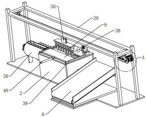
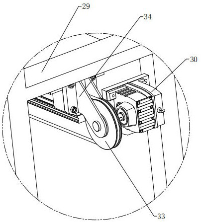
The present invention relates to the technical field of automobile brake pad processing, in particular to an automatic heat treatment equipment for automobile brake pads, which includes a base, and also includes a material transfer mechanism, a material loading mechanism, a material unloading mechanism and a heat treatment mechanism installed on the base. The mechanism includes an oven, a material-holding rotary assembly and two heating pipes. The feeding mechanism includes a material guide assembly, and the unloading mechanism includes a discharge conveyor. One side of the material guide assembly is provided with a loading platform. The internal docking of the material component is set. The material shifting mechanism includes a horizontal moving component, which is horizontally located above the oven. Picking component, the grabbing component includes several jaws that can grab the workpiece, and the top of the oven is equipped with a pick-and-discharge port. This equipment can automatically load and unload materials, and can evenly heat-treat the brake pads, improving heat treatment efficiency and Reduce manpower.

Description

technical field [0001] The invention relates to the technical field of automobile brake pad processing, in particular to an automatic heat treatment equipment for automobile brake pads. Background technique [0002] Brake pads are the most critical safety parts in the vehicle's braking system. The brake pads play a decisive role in the quality of the braking effect. The manufacturing process of brake pads is also constantly improving, and new materials for brake pads are constantly being discovered. At the same time, the change of brake pad manufacturing tools is also inevitable. Brake pads are generally made of steel plates and friction material layers by hot pressing. Most of the technological processes are: powder mixing - thermoforming - heat treatment - grinding - ablation - spraying Powder-packaging, etc. During the production process, the brake pads need to be heat treated. In the existing heat treatment equipment for brake pads, when performing heat processing, there...

Claims


Application Information

Patent Timeline
Patent Type & Authority Patents(China)
IPC IPC(8): C21D9/00
CPCC21D9/0018C21D9/0025C21D9/0068
Inventor 杨亚东
Owner 浙江万赛汽车零部件股份有限公司
Learn More