
Binding packing machine rope gripper

A technology of rope grippers and balers, which is applied to the parts of strapping machinery, etc., can solve the problems of waste of material resources, different quality, complicated structure installation, etc., and achieve the effects of saving material resources, easy operation, and simple installation

Pending Publication Date: 2020-04-14
常州超研机械有限公司
View PDF0 Cites 2 Cited by
  • Summary
  • Abstract
  • Description
  • Claims
  • Application Information

AI Technical Summary

Problems solved by technology

However, the structure of the existing strapping machine rope presser is that the flat clamp rope is squeezed by spring pressure. The material, quality, and thickness of the rope are different, and it is affected by temperature and humidity. The spring pressure cannot adapt to the change in the characteristics of the rope, and the spring pressure is loose. If the rope is not firmly clamped, the rope is easy to loosen and the rope end is easy to fall off, it is easy to cause knots to be tied into false knots or no knots can be tied. The spring pressure is tight and it is easy to gather waste rope ends and waste rope scraps every time, which affects the success rate of knotting. The rope delivery device of the rope gripper of the existing bundling baler must have a back and forth push-pull cylinder, guide rail, and guide rail slider to form a mechanism to push and pull the rope delivery device back and forth to send the rope to the position where the rope is clamped. The structure and installation are complicated and easy to cause frequent failures. , resulting in time-consuming, labor-intensive, waste of material resources

Method used


Image

  • Binding packing machine rope gripper
  • Binding packing machine rope gripper
  • Binding packing machine rope gripper

Examples


Embodiment Construction

[0019] The following will clearly and completely describe the technical solutions in the embodiments of the present invention with reference to the accompanying drawings in the embodiments of the present invention. Obviously, the described embodiments are only some, not all, embodiments of the present invention. Based on the embodiments of the present invention, all other embodiments obtained by persons of ordinary skill in the art without making creative efforts belong to the protection scope of the present invention.

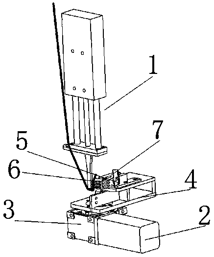
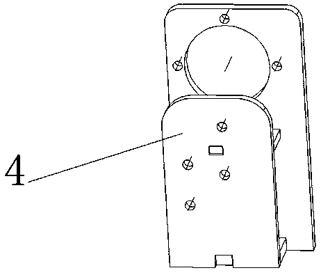
[0020] see Figure 1-5 , in this embodiment: a rope gripper for a bundling baler, comprising a rope feeder 1, a motor 2 is arranged below the rope feeder 1, and the output shaft of the motor 2 is connected to a speed reducer 3, wherein the motor 2 and the speed reducer The model of 3 is RV30. There is a bracket 4 on the top of the reducer 3, which is convenient for installing components. The top of the bracket 4 is fixedly connected with a cutting knife holder...


PUM


Abstract

The invention belongs to the technical field of rope grippers and particularly relates to a binding packing machine rope gripper. The binding packing machine rope gripper comprises a rope feeding device. A motor is arranged below the rope feeding device. An output shaft of the motor is in driving connection with a speed reducer. A support is arranged above the speed reducer. The top of the supportis fixedly connected with a cutter rest. A passive pressing part is arranged on one side of the cutter rest. An active rotary pressing part is arranged on the front side of the passive pressing part.The rope feeding device comprises a rope feeding cylinder, fixed plates, a connecting plate, a round port and a penetration pipe. The front and rear sides of the fixed plates are fixedly connected with the rope feeding cylinder through screws. The binding packing machine rope gripper is provided with the rope feeding device and has the advantages of being higher in stability, easy to operate andcontrol, simple in installation and capable of saving time, labor, cost and material resources. Through cooperation of the active rotary pressing part and the passive pressing part, the binding packing machine rope gripper makes knotting easier and more accurate and increases the knotting success rate remarkably.

Description

technical field [0001] The invention relates to the technical field of rope grippers, in particular to a rope gripper for a bundling baler. Background technique [0002] The baler is also called a strapping machine or a binding machine, which is a kind of baler. It is a machine that wraps the package with a rope and binds it tightly and knots by itself. The baler is generally used to bundle lightweight items. However, the structure of the existing strapping machine rope presser is that the flat clamp rope is squeezed by spring pressure. The material, quality, and thickness of the rope are different, and it is affected by temperature and humidity. The spring pressure cannot adapt to the change in the characteristics of the rope, and the spring pressure is loose. If the rope is not firmly clamped, the rope is easy to loosen and the rope end is easy to fall off, it is easy to cause knots to be tied into false knots or no knots can be tied. The spring pressure is tight and it i...

Claims


Application Information

Patent Timeline
IPC IPC(8): B65B13/18
CPCB65B13/18
Inventor 葛恒超
Owner 常州超研机械有限公司
Learn More