Multi-station self-positioning floating clamping and workpiece self-overturning intelligent tool clamp system

A technology of floating clamping and tooling fixtures, applied in positioning devices, manufacturing tools, metal processing machinery parts, etc., can solve problems such as low production efficiency, poor practicability, complex structure, etc., to improve workpiece production efficiency, ensure safety, reduce Participation effect

Inactive Publication Date: 2020-04-14
QINGDAO TECHNOLOGICAL UNIVERSITY +1
View PDF0 Cites 3 Cited by
  • Summary
  • Abstract
  • Description
  • Claims
  • Application Information

AI Technical Summary

Problems solved by technology

However, the above technical solutions still have the disadvantages of complex structure, only single station, low production efficiency, poor practicability, and not easy to popularize and use.

Method used


Image

  • Multi-station self-positioning floating clamping and workpiece self-overturning intelligent tool clamp system
  • Multi-station self-positioning floating clamping and workpiece self-overturning intelligent tool clamp system
  • Multi-station self-positioning floating clamping and workpiece self-overturning intelligent tool clamp system

Examples


Embodiment 1

[0117] Attached below figure 1 - attached Figure 26 (b) Further explain the clamp system disclosed in this embodiment;

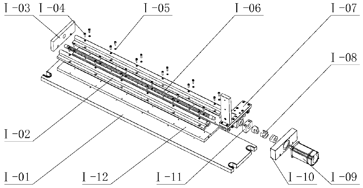
[0118] Refer to attached figure 1 As shown, the multi-station self-positioning floating clamping and workpiece self-turning intelligent fixture system consists of four parts: linear motion device I, workpiece self-turning device II, self-positioning floating clamping device IV, and industrial camera V. Linear motion device I It is installed under the workpiece self-turning device II, and the linear motion device drives the workpiece self-turning device to move horizontally. The workpiece III is placed on each station of the self-positioning floating clamping device IV, and the self-positioning floating clamping device IV and the linear motion device I and the workpiece self-turning device II are placed relatively parallel. Among them, the linear motion device I and the self-positioning floating clamping device IV are fixed on the working platform of the ...

Embodiment 2

[0139] This embodiment discloses the second self-positioning clamping method, which can realize the same function as the self-positioning floating clamping device IV, such as Figure 28 As shown, the bottom plate VI-01 is fixed on the milling machine table through four T-shaped bolts VI-05 and hexagon nuts. There is a positioning support component VI-02 at the left end of the self-positioning floating clamping device, and a positioning support component VI- 02 is fixed on the bottom plate VI-01 by hexagon socket head screws, two linear guide rails VI-07 are fixed on the bottom plate VI-01 by hexagon socket head screws, positioning and floating clamping assembly VI-03 and floating pressing assembly VI-04 can slide left and right on the linear guide rail VI-07, and the hydraulic cylinder VI-06 moves to the left by hydraulically pushing the floating and pressing component VI-04, pressing the workpiece III, and the workpiece III transmits the thrust to the positioning and floating ...


PUM


Abstract

The invention discloses a multi-station self-positioning floating clamping and workpiece self-overturning intelligent tool clamp system which comprises a linear motion device, a workpiece self-overturning device and a self-positioning floating clamping device. The bottom of the workpiece self-overturning device is connected to the linear motion device and is driven by the linear motion device to move horizontally. The self-positioning floating clamping device clamps a workpiece, the workpiece self-overturning device and the self-positioning floating clamping device are oppositely arranged, andthe workpiece self-overturning device can clamp the workpiece and drive the workpiece to overturn. The workpiece self-overturning device comprises a rotary air cylinder, the rotary air cylinder is connected with a hydraulic cylinder, a piston rod of the hydraulic cylinder is connected with a mechanical claw opening and closing finger through a hinge mechanism, and the hydraulic cylinder reciprocates to drive the mechanical claw opening and closing finger to be opened and closed so as to clamp or loosen a workpiece.

Description

technical field [0001] The disclosure belongs to the technical field of process equipment, and in particular relates to a self-positioning fixture used when machining a turning tool plane, in particular to a multi-station self-positioning floating clamping and workpiece self-turning intelligent tooling fixture system. Background technique [0002] A turning tool is a tool for turning that has one cutting portion. Turning tool is one of the most widely used tools in cutting processing, and it is also the basis for learning and analyzing various tools. Turning tools are used on various lathes to process outer circles, inner holes, end faces, threads, grooves, etc. The working part of the turning tool is the part that generates and processes chips, including structural elements such as the blade, the structure that breaks or rolls up chips, the space for chip removal or chip storage, and the passage of cutting fluid. The cutting part of the turning tool is composed of the mai...

Claims


Application Information

Patent Timeline
IPC IPC(8): B23Q3/06B23Q3/08B23Q1/25
CPCB23Q3/06B23Q3/08B23Q1/25B23Q3/082B23Q1/525B23Q3/061B23Q17/249B23Q3/18G06T1/0014G06T7/0004
Inventor 罗亮唐立志张彦彬徐海州李长河杨敏洪华平李昊罡尹硕崔歆刘明政高腾侯亚丽李润泽
Owner QINGDAO TECHNOLOGICAL UNIVERSITY
Why Eureka
Try Eureka