Organic waste gas recovery system and organic waste gas recovery method

A technology of organic waste gas and recovery system, applied in separation methods, chemical instruments and methods, gas treatment, etc., can solve the problems of welding seam detachment, low cooling efficiency, economic loss of users, etc.

Pending Publication Date: 2020-04-14
NINGBO HONGJING ENVIRONMENTAL PROTECTION TECH
View PDF6 Cites 0 Cited by
  • Summary
  • Abstract
  • Description
  • Claims
  • Application Information

AI Technical Summary

Problems solved by technology

[0002] Most of the existing organic waste gas recovery technologies use activated carbon adsorption, and the steam is directly passed into the activated carbon adsorption bed to heat and analyze the activated carbon. Among them, two adsorption beds are generally set up to alternately perform adsorption and desorption; however, after the desorption process, in order to To avoid the welding seam of the adsorption bed being disengaged due to the large temperature difference, usually only the desorbed mixed gas is cooled through the cooler for heat exchange, and then circulated into the adsorption bed for cooling until the internal temperature of the adsorption bed drops to normal temperature, thereby switching To the adsorption mode, the cooling efficiency of this cooling method is not high, and the time-consuming is too long, thereby increasing the operating cost; the adsorption bed will generate adsorption heat during the adsorption work, once the control is not good, there is a safety hazard that is easy to catch fire, the existing adsorption bed structure Since the cooling fan is often used to circulate and cool after the desorption work, the adsorption work and the cooling work cannot be carried out at the same time, so this problem cannot be solved well. Once the adsorption bed catches fire, it will bring greater economic losses to the user.

Method used


Image

  • Organic waste gas recovery system and organic waste gas recovery method
  • Organic waste gas recovery system and organic waste gas recovery method

Examples


Embodiment 1

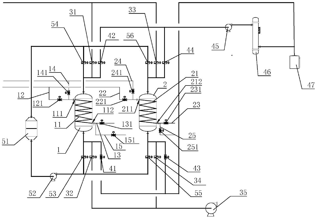
[0026] Embodiment 1: An organic waste gas recovery system, including an alternating adsorption and desorption module, the alternating adsorption and desorption module includes a first adsorption bed 1 and a second adsorption bed 2, and the first adsorption bed 1 is provided with a first steam inlet 111 and the first steam coil 11 of the first steam outlet 112, the second adsorption bed 2 is provided with the second steam coil 21 with the second steam inlet 211 and the second steam outlet 212, the first steam inlet 111 is provided with The first steam inlet pipe 12 of the first steam inlet control valve 121 communicates with the output port of the external steam input device (not shown), and the second steam inlet 211 passes through the second steam inlet pipe provided with the second steam inlet control valve 221 22 communicates with the output port of the external steam input device, the first steam outlet 112 communicates with the first exhaust pipe 13 provided with the first...

Embodiment 2

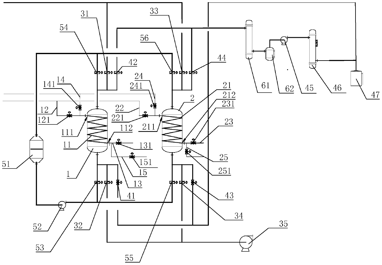
[0030] Embodiment 2: the rest is the same as Embodiment 1, the difference is that the desorption assembly also includes a second cooler 61 and a second storage tank 62, and the second storage tank 62 is provided with an input port at the side and an upper The output port of the second storage tank 62, the input port and the output port of the second storage tank 62 are respectively connected with the inside of the second storage tank 62, and the input port of the second cooler 61 is connected with the first desorption outlet control valve 42 and the first The input port of the adsorption bed 1 is connected, and the input port of the second cooler 61 is also communicated with the second desorption outlet control valve 44 and the input port of the second adsorption bed 2 through pipelines, and the output port of the second cooler 61 is connected through the pipeline. The pipeline communicates with the input port of the second storage tank 62 , and the output port of the second st...

Embodiment 3

[0031] Embodiment 3: The organic waste gas recovery method using the organic waste gas recovery system described in Embodiment 1 includes the following steps:

[0032] Set adsorption time, desorption temperature, continuous desorption time, first cooling temperature and second cooling temperature, and continuously transport organic waste gas through the external organic waste gas input port; where the set desorption temperature range is 100~120°C , the set continuous desorption time range is 1~2 hours, the set first cooling temperature range is 60~75°C, and the set second cooling temperature is 30~35°C

[0033] Synchronously open the first water inlet control valve 141, the first drainage control valve 151, the first adsorption inlet control valve 31 and the first adsorption outlet control valve 32 and close the first steam inlet control valve 121, the first exhaust steam control valve 131, The first desorption inlet control valve 41, the first desorption outlet control va...


PUM


Abstract

The invention discloses an organic waste gas recovery system, which comprises an alternate adsorption and desorption assembly, wherein the alternate adsorption and desorption assembly comprises a first adsorption bed and a second adsorption bed, the first adsorption bed is provided with a first steam coil pipe with a first steam inlet and a first steam outlet, the second adsorption bed is providedwith a second steam coil pipe with a second steam inlet and a second steam outlet, the first steam inlet is communicated with the output port of an external cooling water device through a first waterinlet pipe provided with a first water inlet control valve, the second steam inlet is communicated with the output port of the external cooling water device through a second water inlet pipe providedwith a second water inlet control valve, the first steam outlet is communicated with a first drainage pipe provided with a first drainage control valve, and the second steam outlet is communicated with a second drainage pipe provided with a second drainage control valve. The invention further discloses an organic waste gas recovery method using the organic waste gas recovery system. The system and the method have the advantages of high cooling efficiency in the desorption process, low operation cost and safety in use.

Description

technical field [0001] The invention relates to a waste gas recovery system and a waste gas recovery method, in particular to an organic waste gas recovery system and an organic waste gas recovery method. Background technique [0002] Most of the existing organic waste gas recovery technologies use activated carbon adsorption, and the steam is directly passed into the activated carbon adsorption bed to heat and analyze the activated carbon. Among them, two adsorption beds are generally set up to alternately perform adsorption and desorption; however, after the desorption process, in order to To avoid the welding seam of the adsorption bed being disengaged due to the large temperature difference, usually only the desorbed mixed gas is cooled through the cooler for heat exchange, and then circulated into the adsorption bed for cooling until the internal temperature of the adsorption bed drops to normal temperature, thereby switching To the adsorption mode, the cooling efficien...

Claims


Application Information

Patent Timeline
Patent Type & Authority Applications(China)
IPC IPC(8): B01D53/04B01D5/00
CPCB01D53/0415B01D53/002B01D2257/70B01D2253/102B01D2258/02B01D2259/402B01D2259/416B01D2259/40003
Inventor 李文铃朱海峰
Owner NINGBO HONGJING ENVIRONMENTAL PROTECTION TECH
Why Eureka
Try Eureka