Organic waste gas recovery system

A technology of organic waste gas and recovery system, applied in the direction of gas treatment, steam condensation, membrane technology, etc., can solve problems such as easy fire, weld detachment, economic loss of users, etc.

Inactive Publication Date: 2020-04-14
NINGBO HONGJING ENVIRONMENTAL PROTECTION TECH
View PDF5 Cites 0 Cited by
  • Summary
  • Abstract
  • Description
  • Claims
  • Application Information

AI Technical Summary

Problems solved by technology

[0002] Most of the existing organic waste gas recovery technologies use activated carbon adsorption, and the steam is directly passed into the activated carbon adsorption bed to heat and analyze the activated carbon. Among them, two adsorption beds are generally set up to alternately perform adsorption and desorption; however, after the desorption process, in order to To avoid the welding seam of the adsorption bed being disengaged due to the large temperature difference, usually only the desorbed mixed gas is cooled through the cooler for heat exchange, and then circulated into the adsorption bed for cooling until the internal temperature of the adsorption bed drops to normal temperature, thereby switching To the adsorption mode, the cooling efficiency of this cooling method is not high, and the time-consuming is too long, thereby increasing the operating cost; the adsorption bed will generate adsorption heat during the adsorption work, once the control is not good, there is a safety hazard that is easy to catch fire, the existing adsorption bed structure Since the cooling fan is often used to circulate and cool after the desorption work, the adsorption work and the cooling work cannot be carried out at the same time, so this problem cannot be solved well. Once the adsorption bed catches fire, it will bring greater economic losses to the user.
[0003] After adopting vacuum and thermal indirect heating double activated carbon analysis and regeneration recovery technology, the organic solvent desorbed is taken out of the adsorption bed by vacuuming, and the desorption efficiency is greatly improved. The gas is only condensed by a simple condenser and then stored in the storage tank, and the recovery efficiency of organic substances in a single desorption process is low

Method used


Image

  • Organic waste gas recovery system

Examples


Embodiment Construction

[0014] The present invention will be further described in detail below in conjunction with the accompanying drawings and embodiments.

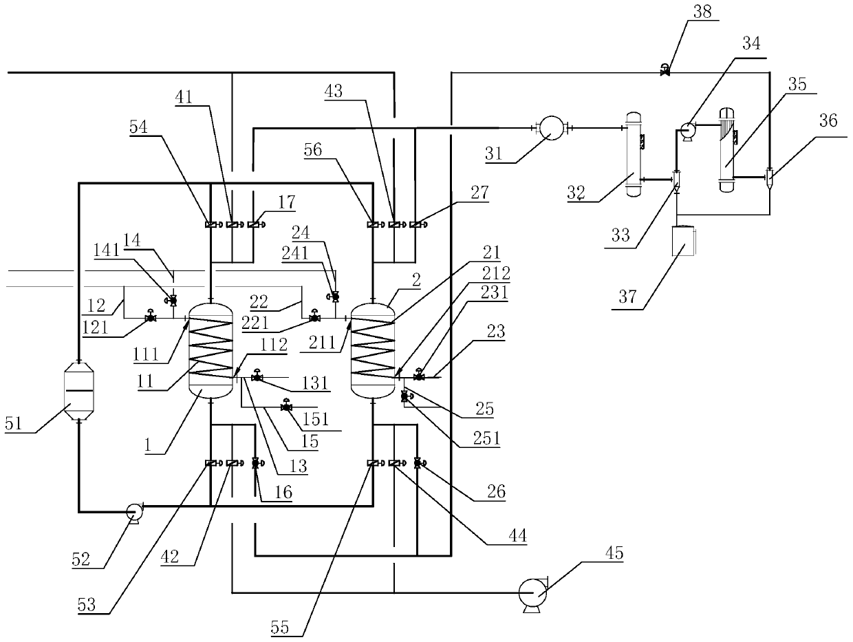
[0015] An organic waste gas recovery system, comprising a first adsorption bed 1, a second adsorption bed 2, a heating assembly, an adsorption assembly, a desorption assembly and a cooling assembly, the heating assembly includes a first steam coil arranged in the first adsorption bed 1 11 and the second steam coil 21 arranged in the second adsorption bed 2, the first steam coil 11 is provided with a first steam inlet 111 and a first steam outlet 112, and the second steam coil 21 is provided with a second steam inlet 211 and the second steam outlet 212, the first steam inlet 111 communicates with the output port of the external steam input device (not shown in the figure) through the first steam inlet pipe 12 provided with the first steam inlet control valve 121, the second steam inlet 211 The second steam inlet pipe 22 provided with the second...


PUM


Abstract

The invention discloses an organic waste gas recovery system, which comprises a first adsorption bed, a second adsorption bed, a heating assembly, an adsorption assembly, a desorption assembly and a cooling assembly, wherein a first steam inlet is communicated with the output port of an external cooling water device through a first water inlet pipe, a second steam inlet is communicated with the output port of the external cooling water device through a second water inlet pipe, the first steam outlet is communicated with a first water discharge pipe, the second steam outlet is communicated witha second water discharge pipe, and the desorption assembly comprises a first desorption inlet control valve, a first desorption outlet control valve, a second desorption inlet control valve, a seconddesorption outlet control valve, a vacuum pump, a first condenser, a first gas-liquid separator, a booster fan, a second condenser, a second gas-liquid separator, a storage tank and a self-operated regulating valve. According to the invention, the recovery efficiency of organic substances in a single desorption process is high, so that the overall economic benefit is improved, the cooling efficiency in the desorption process is high, the cost is effectively reduced, and the use is safe.

Description

technical field [0001] The invention relates to a waste gas recovery system, in particular to an organic waste gas recovery system. Background technique [0002] Most of the existing organic waste gas recovery technologies use activated carbon adsorption, and the steam is directly passed into the activated carbon adsorption bed to heat and analyze the activated carbon. Among them, two adsorption beds are generally set up to alternately perform adsorption and desorption; however, after the desorption process, in order to To avoid the welding seam of the adsorption bed being disengaged due to the large temperature difference, usually only the desorbed mixed gas is cooled through the cooler for heat exchange, and then circulated into the adsorption bed for cooling until the internal temperature of the adsorption bed drops to normal temperature, thereby switching To the adsorption mode, the cooling efficiency of this cooling method is not high, and the time-consuming is too long...

Claims


Application Information

Patent Timeline
IPC IPC(8): B01D53/04B01D5/00
CPCB01D53/0415B01D53/002B01D2257/70B01D2253/102B01D2258/02B01D2259/402B01D2259/40003B01D2259/416B01D2259/40007
Inventor 李文铃朱海峰
Owner NINGBO HONGJING ENVIRONMENTAL PROTECTION TECH
Why Eureka
Try Eureka