Valve plate and hydraulic rotating device

A technology of rotating devices and valve plates, which is applied to components of pumping devices for elastic fluids, liquid fuel engines, machines/engines, etc., and can solve problems such as reduction of opening area, cavitation of valve plates, and negative pressure , to achieve the effect of preventing cavitation, preventing pollution and preventing burning

Active Publication Date: 2020-04-10
株式会社堀内机械 +2
View PDF13 Cites 0 Cited by
  • Summary
  • Abstract
  • Description
  • Claims
  • Application Information

AI Technical Summary

Problems solved by technology

[0003] In the above-mentioned swash plate type hydraulic rotating device (hydraulic pump / motor), when the connection destination of the plunger chamber is switched from the low-pressure port to the high-pressure port, the opening area of ​​the low-pressure port opening to the cylinder port decreases, making it impossible to transfer the fluid. It is fully supplied to the plunger chamber, so the pressure of the hydraulic chamber formed by the plunger and the plunger chamber will become a negative pressure. When the high-pressure port communicates with the cylinder port, the liquid will flow backward from the high-pressure port to the cylinder port. , produce severe pressure fluctuations and discharge flow fluctuations in the plunger chamber
In addition, due to the above-mentioned drastic pressure fluctuations and discharge flow fluctuations, radiation sound on the surface of the plunger pump, pressure pulsation flow, and cavitation are generated, and cavitation occurs on the valve plate.

Method used


Image

  • Valve plate and hydraulic rotating device
  • Valve plate and hydraulic rotating device
  • Valve plate and hydraulic rotating device

Examples


no. 1 Embodiment approach

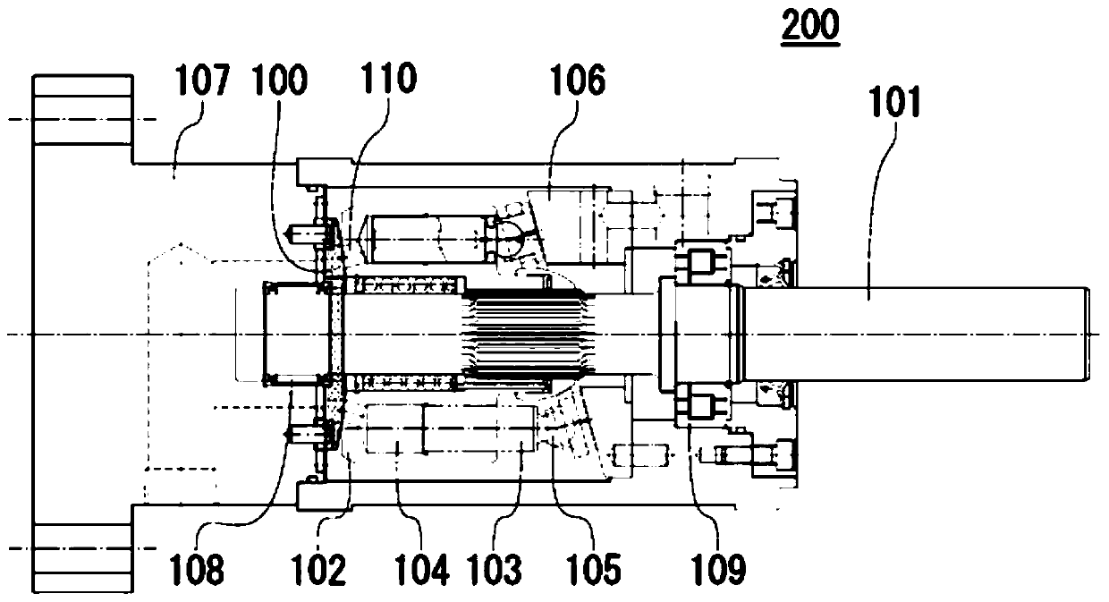
[0069] figure 1 It is a schematic sectional view of the hydraulic rotation device 200 provided with the port plate 100 of 1st Embodiment. The hydraulic rotating device 200 is used for the purpose of pressurizing hydraulic fluid supplied to drivers in industrial machines and construction machines, etc., using an electric motor, an engine, or the like as a power source.

[0070] (Structure of hydraulic turning device 200)

[0071] The hydraulic rotating device 200 includes a rotating shaft 101 , a cylinder 102 , several plungers 103 , several sliding shoes 105 , a swash plate 106 , and a flow plate 100 . The rotary shaft 101 is rotatably supported by bearings 108 and 109 in a housing 107 . Several plunger cavities 104 are formed in the cylinder body 102, and the cylinder body 102 is combined with the rotating shaft 101 and rotates together with the rotating shaft. One end of each plunger chamber 104 is opened at one end of the cylinder 102 , and the other end is opened at th...


PUM


Abstract

The invention provides a valve plate of a hydraulic rotating device and the hydraulic rotating device with the valve plate. The valve plate can prevent cavitation when a connection target of a plungercavity is switched from a low-pressure port to a high-pressure port. The valve plate (100) comprises: a high-pressure port (10) and a low-pressure port (20); and at least one of a trench (30) connected to the wall surface of the high-voltage port (10) and extending in the direction of the low-voltage port (20), and a trench (40) connected to the wall surface of the low-voltage port (20) and extending in the direction of the high-voltage port, wherein a curved surface having a radius of curvature within a predetermined range is formed at a connection portion between the trench and the wall surface.

Description

technical field [0001] The present invention relates to an invention of a distribution plate provided in a hydraulic rotary device, and a hydraulic rotary device (hydraulic pump / motor) equipped with a hydraulic rotary device. Background technique [0002] The swash plate type hydraulic rotating device (hydraulic pump / motor) is composed of a cylinder block, multiple plungers, a swash plate and a distribution plate. The state rotates and reciprocates, and the suction and discharge of each plunger cavity are carried out through the low-pressure side suction port and the high-pressure side discharge port of the valve plate. Specifically, through the low-pressure port of the valve plate, the fluid is sequentially sucked into several plunger chambers, and at the same time, the fluid is discharged from several plunger chambers through the high-pressure port. [0003] In the above-mentioned swash plate type hydraulic rotating device (hydraulic pump / motor), when the connection desti...

Claims


Application Information

Patent Timeline
Patent Type & Authority Applications(China)
IPC IPC(8): F04B53/00F04B1/22
CPCF04B1/2014F04B1/22
Inventor 真下和昌小曾户博
Owner 株式会社堀内机械
Why Eureka
Try Eureka