Three-hole parallel magnetic levitation vacuum tunnel structure
A vacuum tunnel and maglev track technology, applied in tunnels, tunnel systems, tracks, etc., can solve problems such as the impact of vibrations on the surrounding environment, the difficulty of engineering solutions, and the expansion and deformation of pipelines, so as to reduce the use of ground space, improve safety, and take into account The effect of practicality
- Summary
- Abstract
- Description
- Claims
- Application Information
AI Technical Summary
Problems solved by technology
Method used
Image
Examples
Embodiment 1
[0038] figure 1 It is a schematic cross-sectional view of a three-hole parallel maglev vacuum tunnel structure shown in a preferred embodiment. Its main structure is an operating tunnel 1 on both sides, a service tunnel 2 in the middle, and a connecting channel 3 between the three tunnels. The three tunnels are set up in parallel, and the relative distance between the tunnels can be adjusted appropriately according to the topographic and geological conditions of the specific project.
[0039] Specifically, the operating tunnel 1 is a prefabricated or cast-in-place reinforced concrete structure, and its shape can be circular or any other shape that can withstand external loads and vacuum additional loads. The interior is a vacuum environment, and it can also be set in combination with actual engineering. The specific vacuum degree and the size of the tunnel need to meet the requirements of the maglev train 6 for headroom, equipment layout and space requirements for passenger ev...
Embodiment 2
[0043] Optionally, in the scheme of the present invention, the arrangement of the equipment can follow the following principles, small equipment or cables are arranged in the running tunnel 1, and the larger equipment arranged along the running tunnel 1 is arranged in the service tunnel 2, which is convenient for heat dissipation and maintenance, Partially penetrating cables or pipes can be arranged in the cable cavity 11 of the filling 10 under the equipment. For other large-scale equipment with large installation intervals, it can be installed in the shaft or inclined shaft according to the actual project. If the ground has conditions, it can be installed on the ground.
Embodiment 3
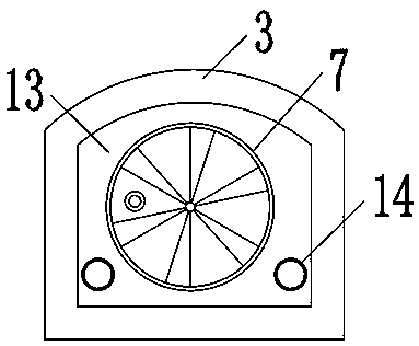
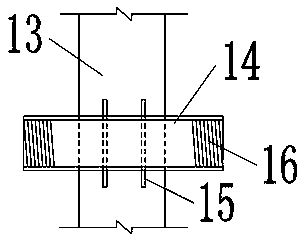
[0045] Figure 2~Figure 3 It is a schematic cross-sectional view of the vacuum isolation wall 13 at the end of the communication passage 3 in a preferred embodiment, including the vacuum isolation door 7 and two reserved wall-through pipes 14 . Vacuum isolation door 7 can be circular, square and other shapes, and the size can accommodate personnel to pass through when evacuating or overhauling. Reserving the wall-piercing pipe 14 can directly be used as a ventilating pipe by connecting pipes at both ends, and also can wear small-diameter pipes or cables inside.
PUM
 Abstract
Description
Claims
Application Information
 - Generate Ideas
- Intellectual Property
- Life Sciences
- Materials
- Tech Scout
- Unparalleled Data Quality
- Higher Quality Content
- 60% Fewer Hallucinations
Browse by: Latest US Patents, China's latest patents, Technical Efficacy Thesaurus, Application Domain, Technology Topic, Popular Technical Reports.
© 2025 PatSnap. All rights reserved.Legal|Privacy policy|Modern Slavery Act Transparency Statement|Sitemap|About US| Contact US: help@patsnap.com


