Eureka AIR delivers breakthrough ideas for toughest innovation challenges, trusted by R&D personnel around the world.

Saw-chip kitchen waste processor

A kitchen waste and processor technology, which is applied to indoor sanitary pipe installations, water supply installations, buildings, etc., can solve the problems of poor shearing effect, unfavorable product promotion, and high cost of ring gear, so as to improve the crushing effect and reduce the Production cost and effect of improving discharge efficiency

Pending Publication Date: 2020-04-10
浙江畅远环保设备有限公司
View PDF3 Cites 1 Cited by
  • Summary
  • Abstract
  • Description
  • Claims
  • Application Information

AI Technical Summary

Problems solved by technology

[0006] In the two types of kitchen waste processors designed above, although the cutting structure is adopted, the grinding structure is no longer used to complete the treatment of kitchen waste. This structural design belongs to the applicant's first-generation product. , it is found that the shearing force can be formed between the cutting knife and the cutting teeth in an ideal state, and the cutting of kitchen waste can be realized, but in fact, due to the relative rotation between the cutting knife and the ring gear, there must be a gap, in fact, the shearing effect Not good, like loosely hinged scissors having difficulty cutting some of the more flexible sheets
[0007] In addition, because the ring gear has a complete ring structure, its tooth edges can only be processed by a lathe or an internal grinder. In terms of technology, it is determined that the tooth edges are actually just the edge of a step on a circular arc surface, arranged like this The ring gear with the tooth blade is like a file, whether it is cut or ground, the effect is not ideal; in addition, the cost of the whole ring gear is high, which is not conducive to the promotion of products

Method used


Image

  • Saw-chip kitchen waste processor
  • Saw-chip kitchen waste processor
  • Saw-chip kitchen waste processor

Examples


Embodiment Construction

[0032] In order to make the technical means, creative features, goals and effects achieved by the present invention easy to understand, the present invention will be further described below in conjunction with specific illustrations.

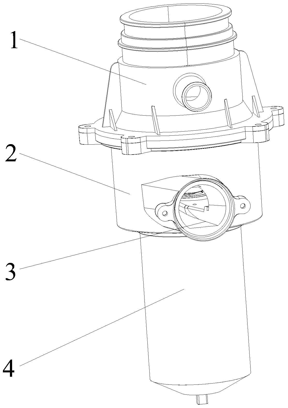
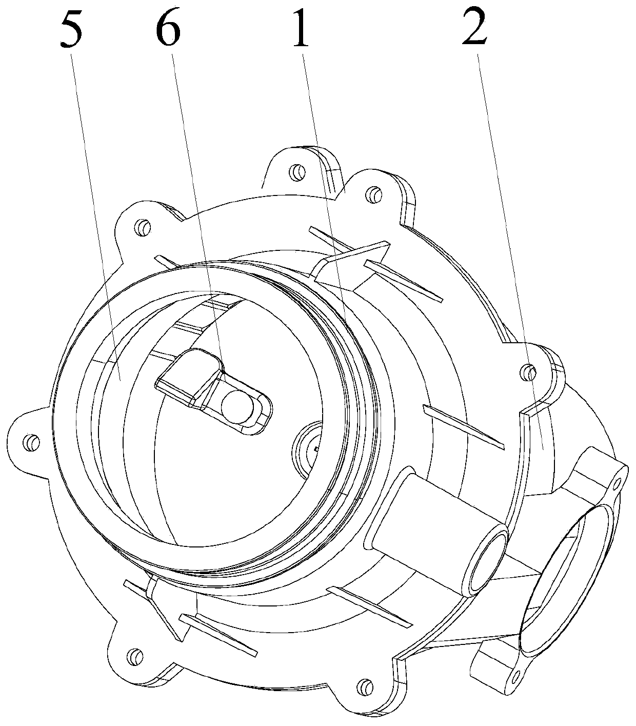
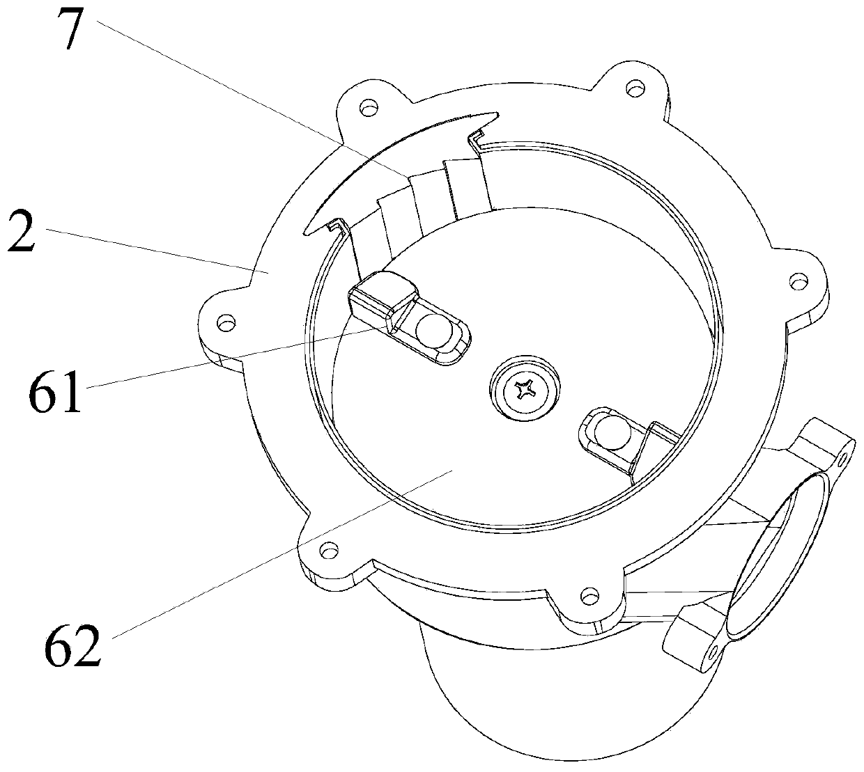
[0033] Such as Figure 1 to Figure 9 As shown, a sawn type kitchen waste disposer provided by the present invention includes a material barrel 1 and a pump casing 2. After the material barrel 1 and the pump casing 2 are assembled, a processing chamber 5 is formed inside, and the processing chamber 5 is provided with The flywheel assembly 6 and the sawtooth block 7, the flywheel assembly 6 is used to drive the rotation of the kitchen waste in the processing chamber 5, the sawtooth block 7 is used to saw the kitchen waste in the rotating state, and the sawtooth block 7 includes several saw blades The units 71 are stacked.

[0034] Wherein, the barrel 1 and the pump casing 2 are combined and assembled, and the barrel 1 and the pump casing 2 are fa...


PUM


Abstract

The invention discloses a saw-chip kitchen waste processor, which comprises a material barrel and a pump shell. After the material barrel and the pump shell are assembled, a treatment cavity is formedinside, the treatment cavity is provided with a flywheel assembly and a sawtooth block, the flywheel assembly is used for driving rotation of kitchen waste in the treatment cavity, and the sawtooth block is used for sawing the kitchen waste in a rotating state. According to the saw-chip kitchen waste processor, by optimizing the design, the sawtooth block in a static state is adopted, the kitchenwaste is sawed and crushed with the sawtooth block due to the centrifugal force, thus the crushing effect is improved, and the saw-chip kitchen waste processor is especially suitable for treatment ofthe waste with large toughness; the sawtooth block is optimized, a saw blade unit overlapping structure is adopted, the production cost is lowered, and later replacement and maintenance are advantageously achieved; and a spiral surface arrangement structure is adopted, swirling current is advantageously to be discharged, and the discharge efficiency is improved.

Description

technical field [0001] The invention relates to the technical field of garbage treatment equipment, in particular to a sawn type kitchen waste processor. Background technique [0002] Kitchen waste disposer generally refers to household kitchen waste disposer, also called household kitchen waste disposer, which is an upgraded product of food waste disposer or kitchen food waste disposer, which can dispose of leftovers, leftovers, vegetable leaves extensively, It can also include fruit peels, fish bones, vegetable stems, egg shells, tea residues, bones, shells, etc. The existing kitchen waste disposer consists of an anti-corrosion grinding chamber, an all-stainless steel grinding hammer, an all-stainless steel grinding disc, and the like. It uses a high-speed rotating permanent magnet motor to drive the turntable in the grinding chamber, and the food waste collides with each other under the action of centrifugal force in a very short time, and the food waste is ground into f...

Claims


Application Information

Patent Timeline
Patent Type & Authority Applications(China)
IPC IPC(8): E03C1/266
CPCE03C1/2665
Inventor 卢能晓
Owner 浙江畅远环保设备有限公司
Why Eureka
Eureka Blog
Learn More