Sawtooth-shaped metal composite plate combining equipment

A metal composite board, zigzag technology, applied in the direction of layered products, lamination devices, lamination, etc., can solve the problems of falling off, can not be automatically pressed, etc., and achieve the effect of precise glue and firm bonding

Inactive Publication Date: 2020-04-10
长兴创智科技有限公司
View PDF0 Cites 1 Cited by
  • Summary
  • Abstract
  • Description
  • Claims
  • Application Information

AI Technical Summary

Problems solved by technology

[0005] The purpose of the present invention is to address the deficiencies of the prior art, realize the transmission of the second composite board by setting the second composite board loading mechanism, and cooperate with the first composite board loading mechanism to realize the transmission of the first composite board and cooperate with the coating The glue component completes the gluing work on the upper surface of the second composite board, and realizes precise glue alignment through the synchronous transmission of the first composite board and the second composite board, so that it can be combined under the action of the guide component, and then the pressing component is used Completing the compression of the bimetallic composite board, thus solving the technical problem that the automatic pressing cannot be performed after the glue is completed, and it may fall off due to external force impact during the transmission process

Method used


Image

  • Sawtooth-shaped metal composite plate combining equipment
  • Sawtooth-shaped metal composite plate combining equipment
  • Sawtooth-shaped metal composite plate combining equipment

Examples


Embodiment 1

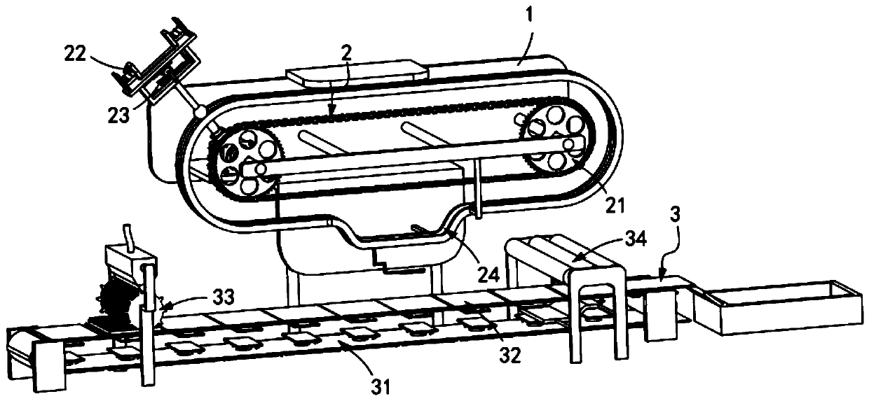
[0056] like figure 1 , Figure 10 As shown, the zigzag metal composite board combination equipment includes a frame 1, and also includes a first composite board loading mechanism 2 and a second composite board loading mechanism 3 installed on the frame 1, and the first composite board loading mechanism Mechanism 2 is located above the second composite plate mounting mechanism 3;

[0057] The first composite board loading mechanism 2 includes a transmission assembly a21, a clamping assembly 22 installed on the transmission assembly a21, and the release of the first composite board 10 on the clamping assembly 22 in cooperation with the clamping assembly 22. Components 23 and guide components 24 positioned below the transport component a21; and

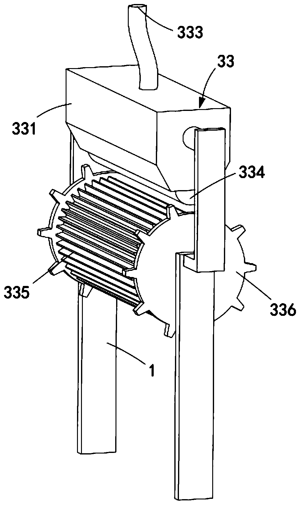
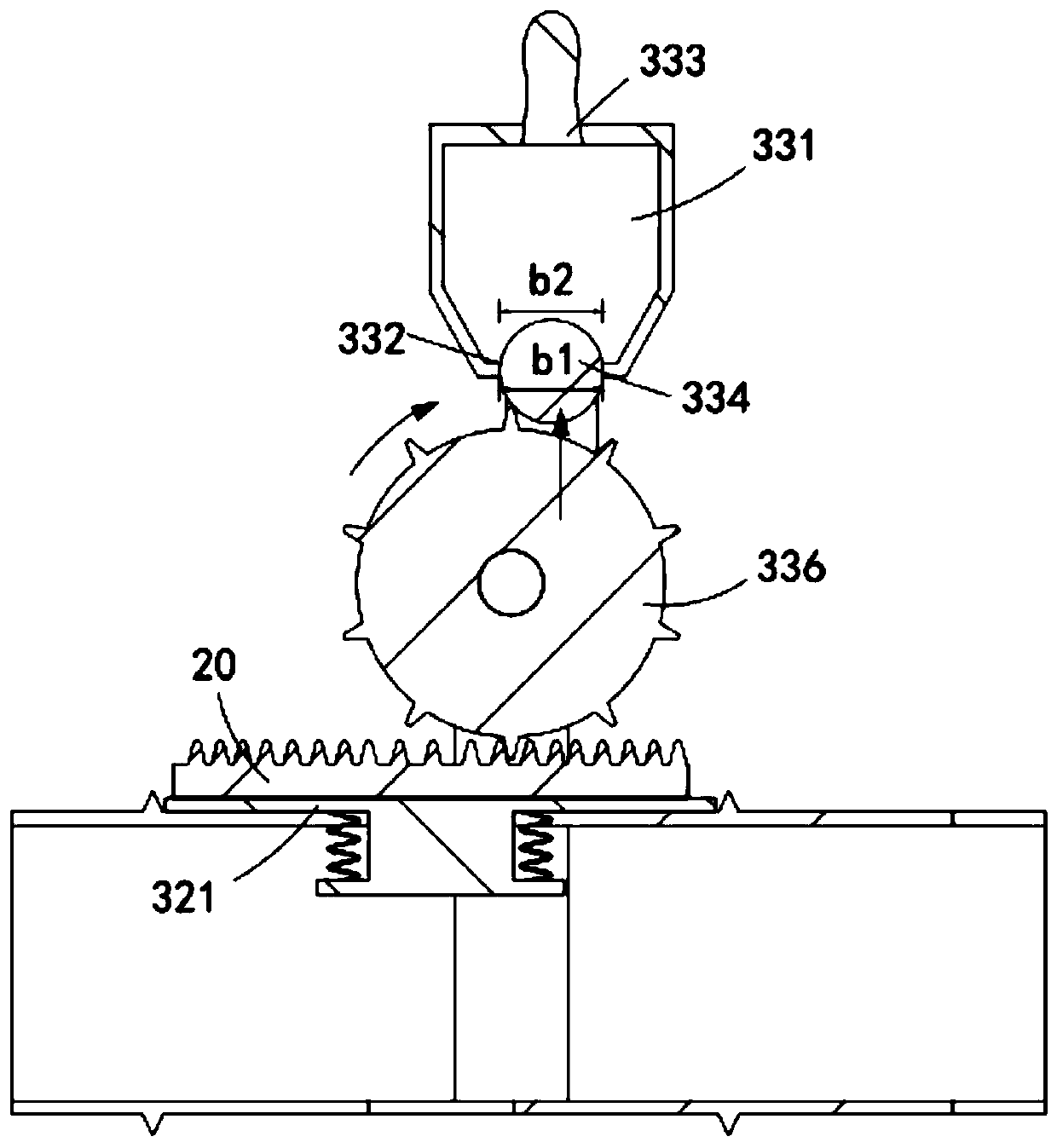
[0058] The second composite board loading mechanism 3 includes a transmission assembly b31, a support assembly 32 installed on the transmission assembly b31, a glue application assembly 33 arranged at the input end of the transmission ...

Embodiment 2

[0094] like Figure 13 , Figure 14 As shown, the components that are the same as or corresponding to those in the first embodiment are marked with the corresponding reference numerals in the first embodiment. For the sake of simplicity, only the differences from the first embodiment will be described below. The difference between this embodiment two and embodiment one is:

[0095] further, such as Figure 13 As shown, the guide assembly 24 is a guide rail a, the guide rail a is installed on the frame 1 and includes an arc portion a241, a horizontal portion a242 and an arc portion b243 of transitional connection; The part a241 is inclined downward along the transmission direction of the transmission assembly a21, and the arc part b243 is inclined upward along the transmission direction of the transmission assembly a21;

[0096] The limit seat 225 is connected with the guide track a in a smooth transition, and there are slide grooves 244 thereon, and the telescopic tube 222 ...


PUM


Abstract

The invention relates to sawtooth-shaped metal composite plate combining equipment which comprises a rack and further comprises a first composite plate loading mechanism and a second composite plate loading mechanism which are installed on the rack, and the first composite plate loading mechanism is located above the second composite plate loading mechanism. The first composite board loading mechanism comprises a conveying assembly a, a clamping assembly, a release assembly and a guide assembly. The second composite board loading mechanism comprises a conveying assembly b, a supporting assembly installed on the conveying assembly b, a gluing assembly arranged at the input end of the conveying assembly b and a pressing assembly arranged at the output end of the conveying assembly b, and thepressing assembly carries out pressing work in the vertical direction on an adhered bimetal composite plate. The bonding surfaces of a first composite plate and a second composite plate are sawtoothplates. The technical problems that automatic pressing cannot be conducted after gluing is completed and falling is possibly caused by external force impact in the conveying process are solved.

Description

technical field [0001] The invention relates to the technical field of metal composite panels, in particular to a zigzag metal composite panel bonding device. Background technique [0002] Bimetal composite board is a new type of composite board prepared by combining two metal plates with different physical, chemical and mechanical properties at the interface through a specific manufacturing method. It can integrate high-strength, high-strength component metal materials Toughness, wear resistance, corrosion resistance and other excellent properties, at the same time, bimetallic composite panels can also save precious metal materials and reduce product costs. At present, the bimetal clad plate produced by the existing rolling method still has problems such as low bonding strength, easy warping, and low yield. [0003] The patent document with the patent number CN2016200821101 discloses an adhesive double metal composite board, including a precious metal plate, an adhesive la...

Claims


Application Information

Patent Timeline
Patent Type & Authority Applications(China)
IPC IPC(8): B32B37/12B32B37/10
CPCB32B37/10B32B37/1284
Inventor 孙鸿珍
Owner 长兴创智科技有限公司
Why Eureka
Try Eureka