Coating device for composite geotextile drainage network

A technology of composite geotechnical and drainage nets, applied in the field of drainage nets, can solve the problems of bonding error, trouble, poor bonding effect, etc., and achieve the effects of close front and rear connection, firm bonding and high degree of automation

Active Publication Date: 2020-04-07
山东恒阳新材料有限公司
View PDF8 Cites 0 Cited by
  • Summary
  • Abstract
  • Description
  • Claims
  • Application Information

AI Technical Summary

Problems solved by technology

[0005] The purpose of the present invention is to address the deficiencies of the prior art, realize the transmission of the drainage network by setting the drainage net loading mechanism, and cooperate with the single-side coating top loading mechanism to realize the synchronous transmission of the coating, and then realize the relative in the transmission work. Under static working conditions, the precise glue alignment of the two is completed to make them composite, and then the cladding is bonded to the drainage net by using the flattening compound mechanism and spread to both sides, thus solving the problem of manually separating the upper cladding and the lower cladding. It is more troublesome to bond the layers on the drainage net through adhesives, errors may occur in the bonding work, and the technical problem of poor bonding effect at the same time

Method used


Image

  • Coating device for composite geotextile drainage network
  • Coating device for composite geotextile drainage network
  • Coating device for composite geotextile drainage network

Examples


Embodiment 1

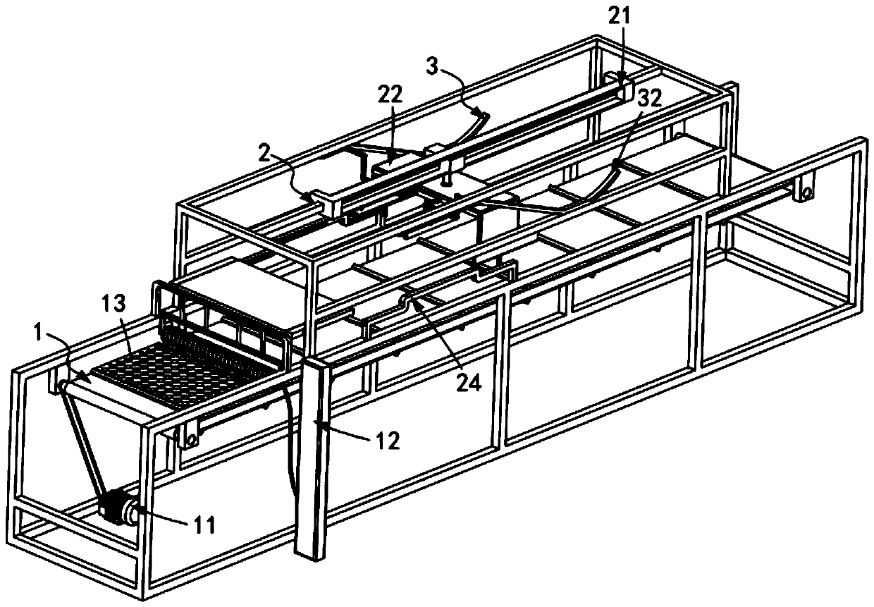
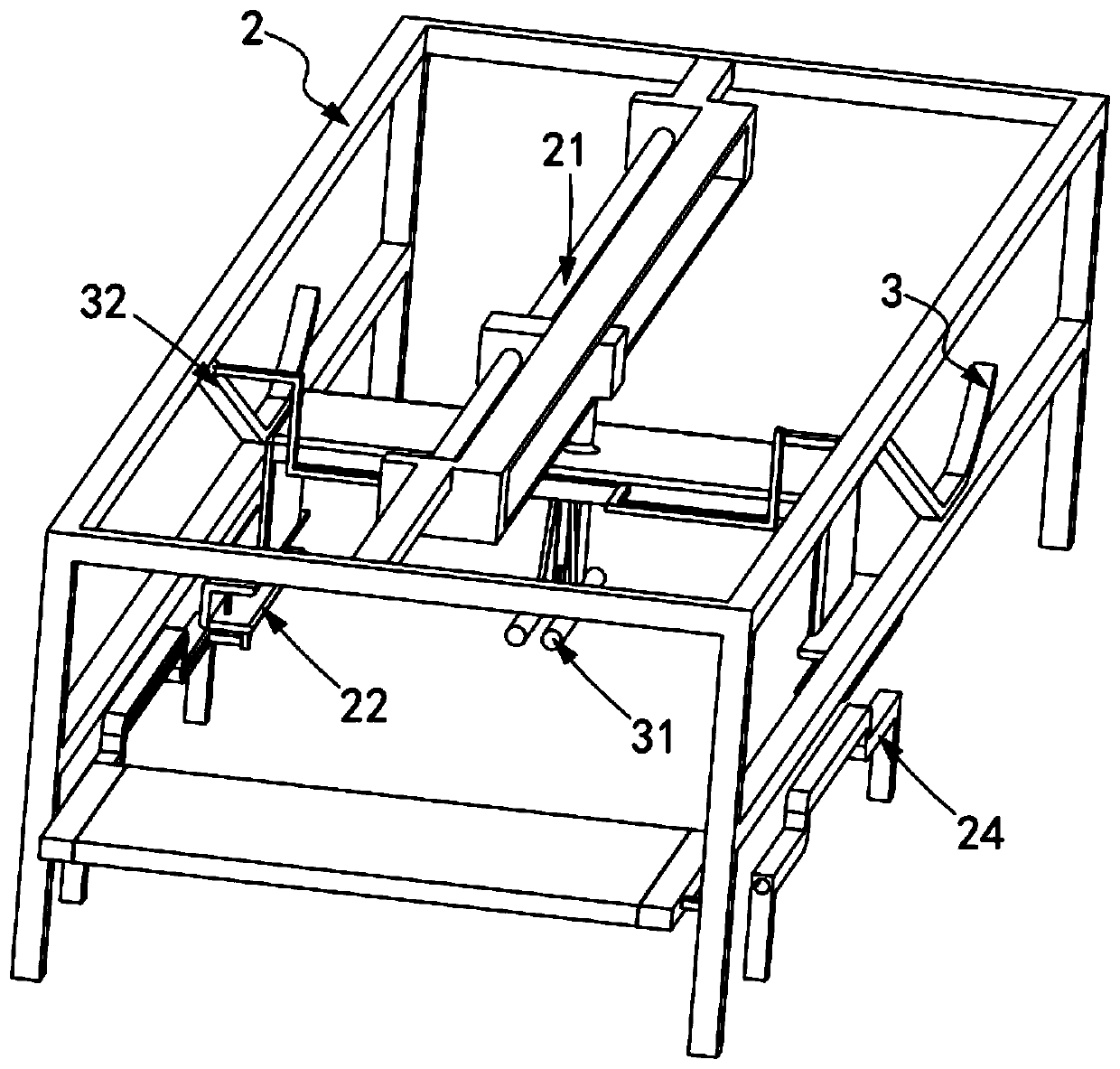
[0060] Such as figure 1 and figure 2 As shown, a cladding device for a composite geotechnical drainage net, comprising:

[0061] Drainage net installation mechanism 1, said drainage net installation mechanism 1 includes a first transmission assembly 11 and a brushing assembly 12 arranged in the input direction of said first transmission assembly 11, and drainage nets 13 are sequentially placed on said first transmission assembly 11 superior;

[0062] A single-sided cladding upper-loading mechanism 2, the single-sided cladding upper-loading mechanism 2 includes a second transmission assembly 21, a clamping assembly 22 along the transmission direction of the second transmission assembly 21, and a clamping assembly 22 for driving the clamping assembly 22 supports a control assembly 24 of coating 23 in transit; and

[0063] The flattening composite mechanism 3, the flattening composite mechanism 3 includes a spreading component 31 that flattens the coating 23 on the clamping c...

Embodiment 2

[0097] Such as Figure 5 As shown, the components that are the same as or corresponding to those in the first embodiment are marked with the corresponding reference numerals in the first embodiment. For the sake of simplicity, only the differences from the first embodiment will be described below. The difference between this embodiment two and embodiment one is:

[0098] further, such as Figure 5 As shown, the second transmission assembly 21 includes a transmission track 211, a rodless cylinder 212 installed on the transmission track 211, a mounting seat 213 matched and slidably arranged in the transmission track 211, and a rodless Synchronous tracking annunciator on the cylinder 212, the output end of the transmission track 211 is provided with a distance sensor;

[0099] The mounting base 213 is connected to the sliding part of the rodless cylinder 212 .

[0100] In this embodiment, by setting a synchronous tracking signal device, its function is to ensure that the recip...


PUM


Abstract

The invention relates to a coating device for a composite geotextile drainage network, and the coating device comprises a drainage network loading mechanism, a single-sided coating loading mechanism and a flattening composite mechanism. The drainage network loading mechanism comprises a first transmission assembly and a brushing assembly arranged in the input direction of the first transmission assembly, and the drainage network is sequentially placed on the first transmission assembly; the single-sided coating loading mechanism comprises a second transmission assembly, a clamping assembly inthe transmission direction of the second transmission assembly, and a control assembly for driving the clamping assembly to support a coating in transmission; and the flattening composite mechanism comprises an unfolding assembly for flattening the coating on the clamping assembly and covering the drainage network, and an adjusting assembly for driving the unfolding assembly to move up and down inthe vertical direction. The technical problems that manually adhering of an upper covering layer and a lower covering layer to the drainage network through an adhesive is troublesome, errors possiblyoccur in adhering, and the adhering effect is poor are solved.

Description

technical field [0001] The invention relates to the technical field of drainage nets, in particular to a cladding device for a composite geotechnical drainage net. Background technique [0002] Composite drainage network is an important part of civil engineering drainage equipment. Under northern climate conditions, the laying of composite drainage nets can help reduce the impact of frost heave. If the freezing depth is deep, the drainage nets can be laid at a shallower position in the foundation to block capillary action. In addition, it is often necessary to use non-freezing Replacement of expansive granular subbase, extending down to freezing depths; laid between foundations and sub-bases to drain water accumulated between sub-bases, block capillary water and effectively incorporate into edge drainage, which This structure automatically shortens the drainage path of the foundation, greatly shortens the drainage time, and can reduce the use of selected foundation material...

Claims


Application Information

Patent Timeline
IPC IPC(8): B29C65/52B29C65/78B29L28/00
CPCB29C65/526B29C65/7841B29C65/7861B29L2028/00
Inventor 李孟朋
Owner 山东恒阳新材料有限公司
Why Eureka
Try Eureka