Corrugated interface bimetal composite plate forming method

A forming method and composite board technology, applied in the direction of chemical instruments and methods, lamination devices, lamination auxiliary operations, etc., can solve the problems of affecting aesthetics and wasting raw materials, so as to achieve more firm bonding and facilitate continuous control of output Effect

Inactive Publication Date: 2020-04-28
长兴创智科技有限公司
View PDF0 Cites 1 Cited by
  • Summary
  • Abstract
  • Description
  • Claims
  • Application Information

AI Technical Summary

Problems solved by technology

[0005] The purpose of the present invention is to address the deficiencies of the prior art, and realize the automatic gluing work of the second composite board by setting the loading work of the second composite board to cooperate with the gluing work of the second composite board, and cooperate with the synchronously conveyed first composite board. The board loading work completes the automatic bonding and forming of the bimetallic composite board, and then uses the bimetallic composite board to press the work, so that the first composite board and the second composite board are firmly bonded together to avoid external impact during transmission and output. , through the bonding method, the non-adhesive surfaces of the first composite board and the second composite board are smooth surfaces, thus solving the problem of bundling on the surface that affects the aesthetics and waste of raw materials in some working conditions, such as the pipeline field technical problem

Method used


Image

  • Corrugated interface bimetal composite plate forming method
  • Corrugated interface bimetal composite plate forming method
  • Corrugated interface bimetal composite plate forming method

Examples


Embodiment 1

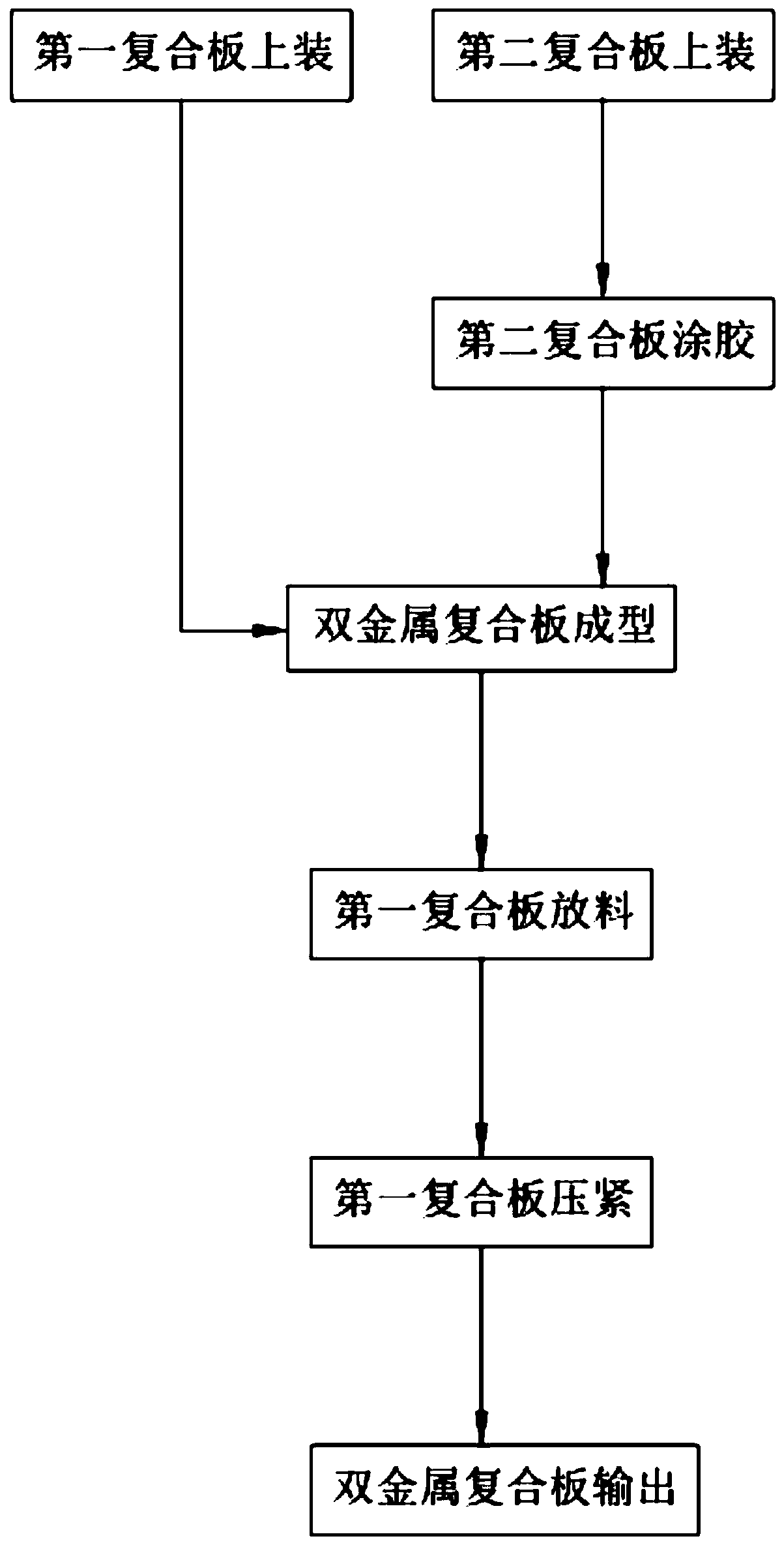
[0073] like figure 1 As shown, a corrugated interface bimetallic composite plate forming method includes:

[0074] Step 1, install the first composite board, manually pull back the two groups of splints 2243 of the clamping assembly 22, then place the first composite board 10 on the installation frame 223, and use the reset of the compression spring 2242, the two groups of splints 2243 Clamp the two sets of splints 2243 to make them drive backward along the transmission assembly a21;

[0075] Step 2, the second composite board is installed, and in synchronization with the step 1, the second composite board 20 is manually placed on the supporting plate 321 of the supporting component 32, and is driven backward along with the transmission component b31;

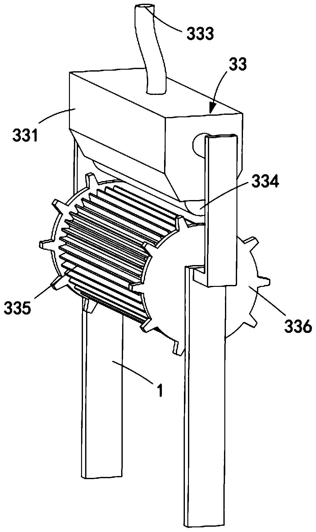
[0076] Step 3, the second composite board is glued, the second composite board 20 being conveyed is meshed with the feeding roller 335 and rotated, and the synchronous bump 336 is set in discontinuous contact with the floating...

Embodiment 2

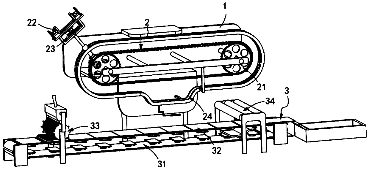
[0092] like figure 2 , Figure 11 As shown, a zigzag metal composite plate bonding equipment includes a frame 1, and also includes a first composite plate mounting mechanism 2 and a second composite plate mounting mechanism 3 installed on the frame 1, the first composite plate The plate mounting mechanism 2 is located above the second composite plate mounting mechanism 3;

[0093] The first composite board loading mechanism 2 includes a transmission assembly a21, a clamping assembly 22 installed on the transmission assembly a21, and the release of the first composite board 10 on the clamping assembly 22 in cooperation with the clamping assembly 22. Components 23 and guide components 24 positioned below the transport component a21; and

[0094] The second composite board loading mechanism 3 includes a transmission assembly b31, a support assembly 32 installed on the transmission assembly b31, a glue application assembly 33 arranged at the input end of the transmission assemb...

Embodiment 3

[0130] like Figure 14 As shown, the parts that are the same as or corresponding to those in the second embodiment are marked with the corresponding reference numerals in the second embodiment. For the sake of simplicity, only the differences from the second embodiment will be described below. The difference between this embodiment three and embodiment two is:

[0131] further, such as Figure 14 As shown, the guide assembly 24 is a guide rail a, the guide rail a is installed on the frame 1 and includes an arc portion a241, a horizontal portion a242 and an arc portion b243 of transitional connection; The part a241 is inclined downward along the transmission direction of the transmission assembly a21, and the arc part b243 is inclined upward along the transmission direction of the transmission assembly a21;

[0132] The limit seat 225 is connected with the guide track a in a smooth transition, and there are slide grooves 244 thereon, and the telescopic tube 222 is provided wi...


PUM

PropertyMeasurementUnit
Thicknessaaaaaaaaaa

Abstract

The invention relates to a corrugated interface bimetal composite plate forming method. The method comprises the steps of: 1, mounting a first composite board; 2, mounting a second composite board; 3,gluing the second composite board, enabling the conveyed second composite board to rotate in a manner of being engaged with a feeding roller, enabling a synchronous convex block to be in intermittentcontact with a floating and sinking roller, enabling glue in a gluing box to drip outwards from a discharge port and flow into the feeding roller when the convex part of the convex block is in contact with the floating and sinking roller, and enabling the feeding roller to rotate to uniformly coat the second composite board with the glue; 4, forming a bimetal composite board; 5, discharging the first composite board; 6, pressing the bimetal composite board; and 7, outputting the bimetal composite board. The technical problems that the attractiveness is affected and raw materials are wasted due to the fact that the surface is bundled under partial working conditions such as the field of pipelines are solved.

Description

technical field [0001] The invention relates to the technical field of bimetallic composite panels, in particular to a method for forming bimetallic composite panels with corrugated interfaces. Background technique [0002] Double composite board is a kind of composite material. Because it has the advantages of two kinds of metals, it is widely used in aerospace, weapon manufacturing, home appliances and other fields. With the exploitation of natural resources and the increasing energy consumption this year, many mineral resources, especially chromium and nickel resources, are on the verge of depletion, and the advantages of composite materials in saving rare metals are gradually highlighted. [0003] The patent document with the patent number CN201810711027X discloses a continuous rolling method of bimetallic clad plates with a corrugated interface. First, corrugated rollers are used to roll the billet into a corrugated clad plate to form a stress peak at the trough of the ...

Claims


Application Information

Patent Timeline
IPC IPC(8): B32B37/10B32B37/12B32B38/18
CPCB32B37/10B32B37/1284B32B38/18B32B38/1841
Inventor 孙鸿珍
Owner 长兴创智科技有限公司
Why Eureka
Try Eureka