
A device for improving sncr denitrification efficiency of circulating fluidized bed boiler

A technology of circulating fluidized bed and denitration efficiency, which is applied in the field of devices for improving SNCR denitration efficiency of circulating fluidized bed boilers, can solve the problems of reduced probability of chemical reaction, low mutual collision, and reduced denitration efficiency, etc., so as to improve the degree of reaction and reduce the Activation energy, the effect of improving denitration efficiency

Active Publication Date: 2021-09-21
HUNAN UNIV OF HUMANITIES SCI & TECH
View PDF6 Cites 0 Cited by
  • Summary
  • Abstract
  • Description
  • Claims
  • Application Information

AI Technical Summary

Problems solved by technology

NH in the existing selective non-catalytic reduction (SNCR) denitrification process 3 (Ammonia) molecules and NO (nitrogen monoxide) molecules in the flue gas collide with each other under the action of airflow, and then carry out the above chemical reaction at high temperature, so as to achieve the purpose of flue gas denitrification, but due to the gas flow velocity Faster NH 3 Molecules and NO molecules in the flue gas have a low probability of colliding with each other in the same gas flow, resulting in NH 3 The probability of chemical reaction between the molecules and the NO molecules in the flue gas is reduced, thereby reducing the denitrification efficiency

Method used


Image

  • A device for improving sncr denitrification efficiency of circulating fluidized bed boiler
  • A device for improving sncr denitrification efficiency of circulating fluidized bed boiler
  • A device for improving sncr denitrification efficiency of circulating fluidized bed boiler

Examples


Embodiment Construction

[0021] The following will clearly and completely describe the technical solutions in the embodiments of the present invention with reference to the accompanying drawings in the embodiments of the present invention. Obviously, the described embodiments are only some, not all, embodiments of the present invention. Based on the embodiments of the present invention, all other embodiments obtained by persons of ordinary skill in the art without creative efforts fall within the protection scope of the present invention.

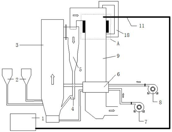
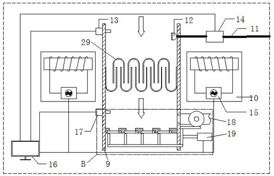
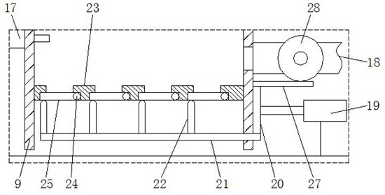
[0022] see Figure 1-4 , the present invention provides a technical solution: a device for improving the SNCR denitrification efficiency of a circulating fluidized bed boiler, comprising a feed bin 2, a circulating fluidized bed boiler furnace 3 and a shaft flue 9, the lower end of the circulating fluidized bed boiler furnace 3 It is connected with the feed bin 2, and the feed bin 2 is used to deliver fuel to the furnace 3 of the circulating fluidized bed boiler, a...


PUM


Abstract

The invention relates to the technical field of boiler denitration, in particular to a device for improving the SNCR denitrification efficiency of a circulating fluidized bed boiler, comprising a feed bin, a circulating fluidized bed boiler furnace and a shaft flue, the lower end of the circulating fluidized bed boiler furnace and the feed bin Connection, the upper end of the circulating fluidized bed boiler furnace is connected to the separation and return mechanism, the upper and lower ends of the separation and return mechanism are respectively connected with the upper end of the shaft flue and the lower end of the circulating fluidized bed boiler furnace, and the lower end of the circulating fluidized bed boiler furnace is connected Oxygen supply mechanism, the upper end of the shaft flue is provided with a denitrification mechanism. This device for improving the SNCR denitrification efficiency of circulating fluidized bed boilers generates a changing magnetic field through an electromagnetic generator, so that NH 3 The charged ions or ion clusters that are ionized after the violent collision between the molecules and the NO molecules in the flue gas are under the action of the changing magnetic field force generated by the alternating current, which increases the probability of collision and the severity of the collision, making the reaction degree correspondingly increased and reduced. Chemical reaction activation energy, thereby improving the denitrification efficiency.

Description

technical field [0001] The invention relates to the technical field of boiler denitrification, in particular to a device for improving the SNCR denitrification efficiency of a circulating fluidized bed boiler. Background technique [0002] At present, the chemical reaction process in selective non-catalytic reduction (SNCR) denitrification is mainly to use ammonia to reduce nitric oxide, and the overall chemical reaction can be summarized as: NH 3 +NO+O 2 →H 2 O+N 2 . NH in the existing selective non-catalytic reduction (SNCR) denitrification process 3 (Ammonia) molecules and NO (nitrogen monoxide) molecules in the flue gas collide with each other under the action of airflow, and then carry out the above chemical reaction at high temperature, so as to achieve the purpose of flue gas denitrification, but due to the gas flow velocity Faster NH 3 Molecules and NO molecules in the flue gas have a low probability of colliding with each other in the same gas flow, resulting...

Claims


Application Information

Patent Timeline
Patent Type & Authority Patents(China)
IPC IPC(8): B01D53/79B01D53/56B01D53/78F23J15/00
CPCB01D53/346B01D53/56B01D53/78B01D53/79B01D2251/2062B01D2258/0283F23J15/006F23J2215/10F23J2215/101
Inventor 刘海力张旭洪庆超刘浩宇陈旺许君
Owner HUNAN UNIV OF HUMANITIES SCI & TECH
Learn More