
Screen printing device and back grid line alignment method of double-sided battery

A technology of screen printing device and double-sided battery, which is applied in the direction of screen printing machine, printing, printing machine, etc., can solve the problems of large contrast ratio, high surface reflectivity, and inability to judge alignment in time, so as to improve double-sided The effect of surface efficiency

Pending Publication Date: 2020-04-03
CSI CELLS CO LTD +1
View PDF0 Cites 1 Cited by
  • Summary
  • Abstract
  • Description
  • Claims
  • Application Information

AI Technical Summary

Problems solved by technology

[0005] However, due to the presence of many irregular grain boundaries in polysilicon and the high reflectivity of the surface after diamond wire cutting, the conventional screen printing process cannot be used for alignment due to the large contrast between different grains when making double-sided cells. Point recognition for precise alignment
If the edge-finding function of the camera is used for alignment, and it is impossible to judge whether the alignment is accurate in time, it is very easy to cause low-efficiency films due to alignment failure during the production process, and there is a greater risk

Method used


Image

  • Screen printing device and back grid line alignment method of double-sided battery
  • Screen printing device and back grid line alignment method of double-sided battery
  • Screen printing device and back grid line alignment method of double-sided battery

Examples


Embodiment Construction

[0030] The application will be described in detail below in conjunction with the specific implementations shown in the drawings. However, these embodiments do not limit the application, and the structural, method, or functional changes made by those skilled in the art according to these embodiments are all included in the protection scope of the application.

[0031] In each figure of the present application, for the convenience of illustration, some dimensions of the structure or part will be exaggerated relative to other structures or parts, therefore, only used to illustrate the basic structure of the subject of the present application.

[0032] In addition, terms such as "upper", "above", "below", "below" and the like used herein to indicate a relative position in space are for ease of explanation to describe a unit or feature as shown in the drawings relative to The relationship of another unit or feature. The term of the relative position in space may be intended to include ...


PUM

PropertyMeasurementUnit
Light source wavelengthaaaaaaaaaa

Abstract

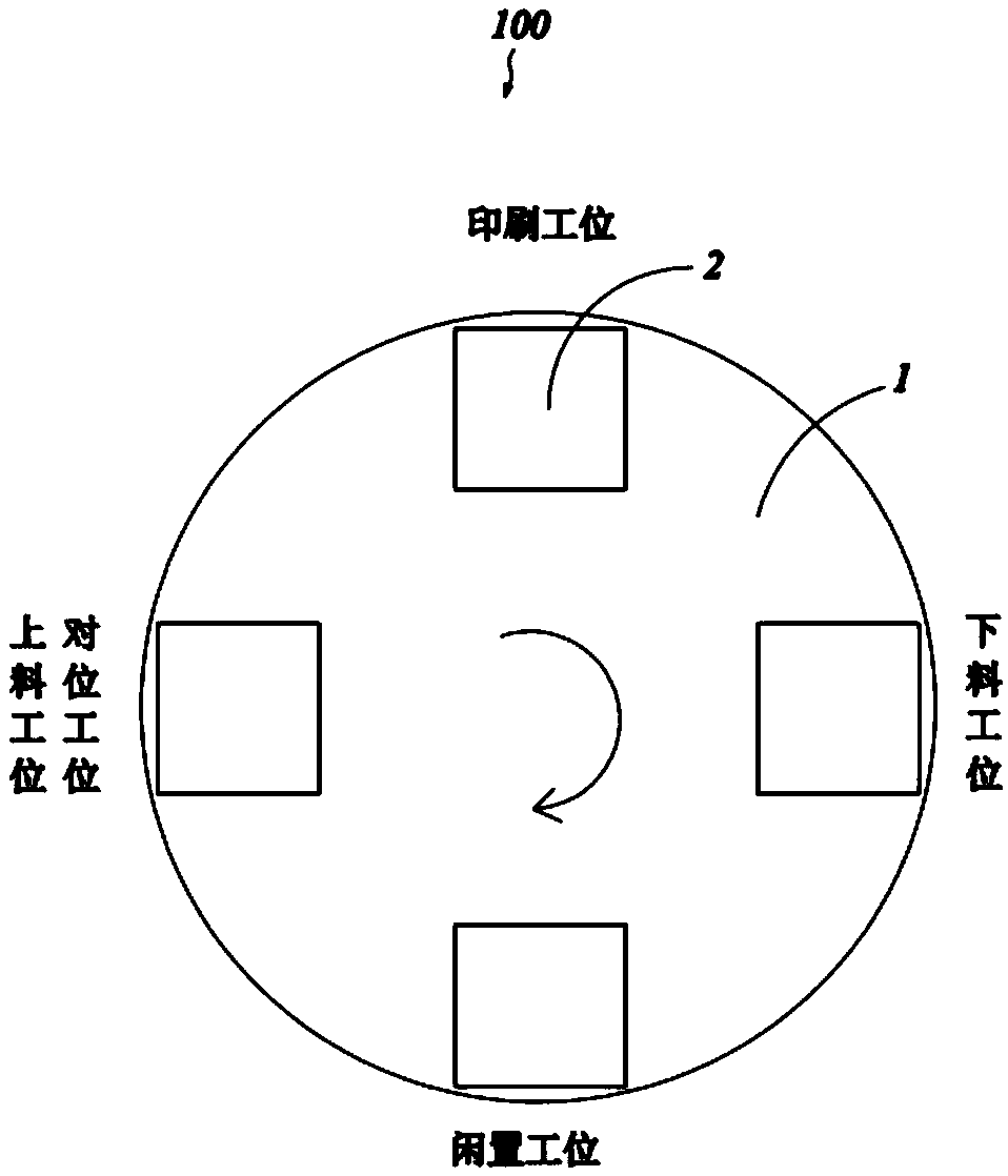
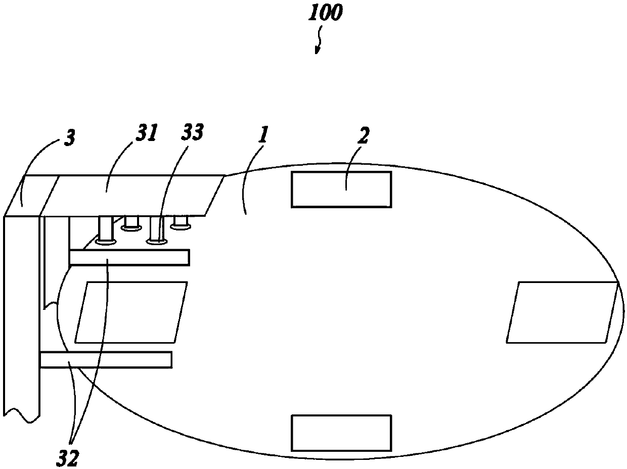
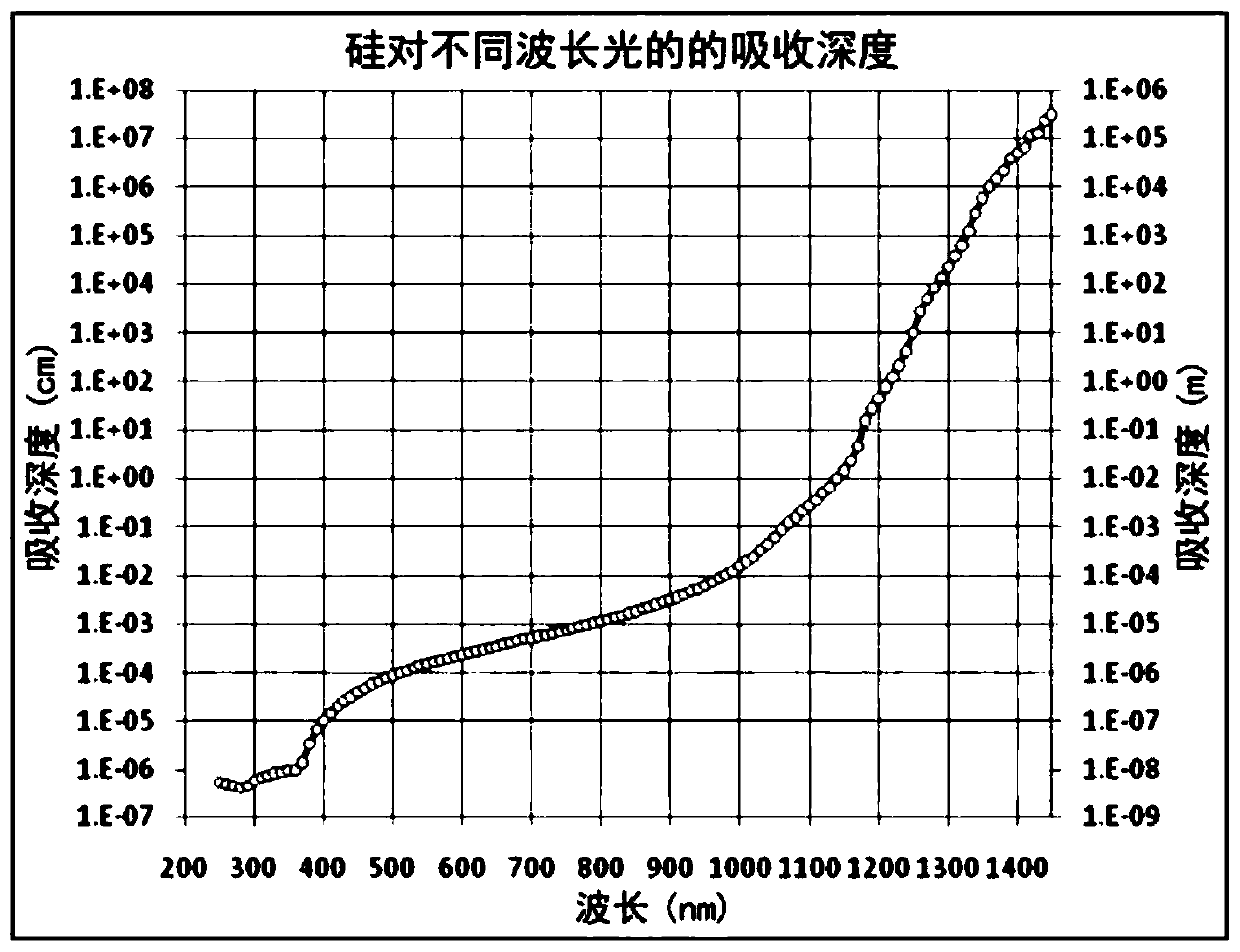
The invention provides a silk screen printing device. The device comprises a rotary disc, wherein a positioning station and a printing station are sequentially arranged in the circumferential direction of the rotary disc; at least one printing table which is arranged on the rotary disc, wherein when the rotary disc rotates, the printing table is driven to rotate to the positioning station and theprinting station; a positioning system which is located at the positioning station and comprises an infrared light source and an alignment camera, wherein when the printing table rotates to the alignment station, the infrared light source and the alignment camera are both located above the printing table; and a printing system which is located at the printing station and is in communication connection with the positioning system. According to the silk screen printing device, the infrared light source emits infrared light to the back surface of a silicon wafer, and the alignment camera capturesreflected light of the infrared light on the back surface of the silicon wafer to form an image, so that the position of a positioning pattern can be accurately obtained, and back surface grid linescan be accurately printed; and the width of the back grid line is reduced to 140 microns, so that the double-sided efficiency of the double-sided cell is improved.

Description

Technical field [0001] The invention relates to the field of crystalline silicon solar cells, and in particular to a screen printing device capable of accurately printing back grid lines of polycrystalline silicon double-sided cells and single-crystal silicon double-sided cells, and a method for aligning the back grid lines of double-sided cells. Print back grid lines. Background technique [0002] Conventional fossil fuels are increasingly depleted and pollute the environment. Among all renewable energy sources, solar energy has been rapidly developed as an ideal clean energy source to replace fossil fuels. Photovoltaic power generation is widely used worldwide as an effective means of utilizing solar energy. At present, among all solar cells, crystalline silicon solar cells are currently one of the mainstream in the field of photovoltaic power generation. This is due to the extremely rich reserves of silicon materials in the earth's crust, as well as excellent electrical and m...

Claims


Application Information

Patent Timeline
IPC IPC(8): H01L31/18H01L21/68H01L31/0224B41F15/08
CPCH01L21/681H01L31/1804H01L31/022441B41F15/08Y02P70/50
Inventor 陈曦熊光涌
Owner CSI CELLS CO LTD
Learn More