
Power control hydraulic system and crane

A power control and hydraulic system technology, applied in the field of crane hydraulic system and power control hydraulic system, can solve the problems of main engine cost, increased fuel consumption later maintenance cost, unadjustable power required by load, etc., to achieve the effect of large selection space

Active Publication Date: 2020-04-03
ZOOMLION HEAVY IND CO LTD
View PDF8 Cites 2 Cited by
  • Summary
  • Abstract
  • Description
  • Claims
  • Application Information

AI Technical Summary

Problems solved by technology

[0006] 1. When the engine speed is constant, the power required by the load cannot be adjusted;
[0007] 2. In the case of constant speed, special working conditions (such as overhaul, maintenance, etc.) have much higher requirements on engine output power than other working conditions, so a higher-power engine should be selected; and a higher-power The use of high-quality engines will lead to increased host costs, fuel consumption, and post-maintenance costs

Method used


Image

  • Power control hydraulic system and crane
  • Power control hydraulic system and crane
  • Power control hydraulic system and crane

Examples


Embodiment Construction

[0053] Specific embodiments of the present invention will be described in detail below in conjunction with the accompanying drawings. It should be understood that the specific embodiments described here are only used to illustrate and explain the present invention, and are not intended to limit the present invention.

[0054] In addition, the terms "first", "second", and "third" are only used for descriptive purposes, and cannot be interpreted as indicating or implying relative importance or implicitly specifying the number of indicated technical features. The features of "first", "second", and "third" may expressly or implicitly include one or more of said features.

[0055]In the description of the present invention, it should be noted that, unless otherwise clearly stipulated and limited, the terms "installation", "installation" and "connection" should be understood in a broad sense, for example, it can be a fixed connection or a detachable connection. A connection, or an ...


PUM


Abstract

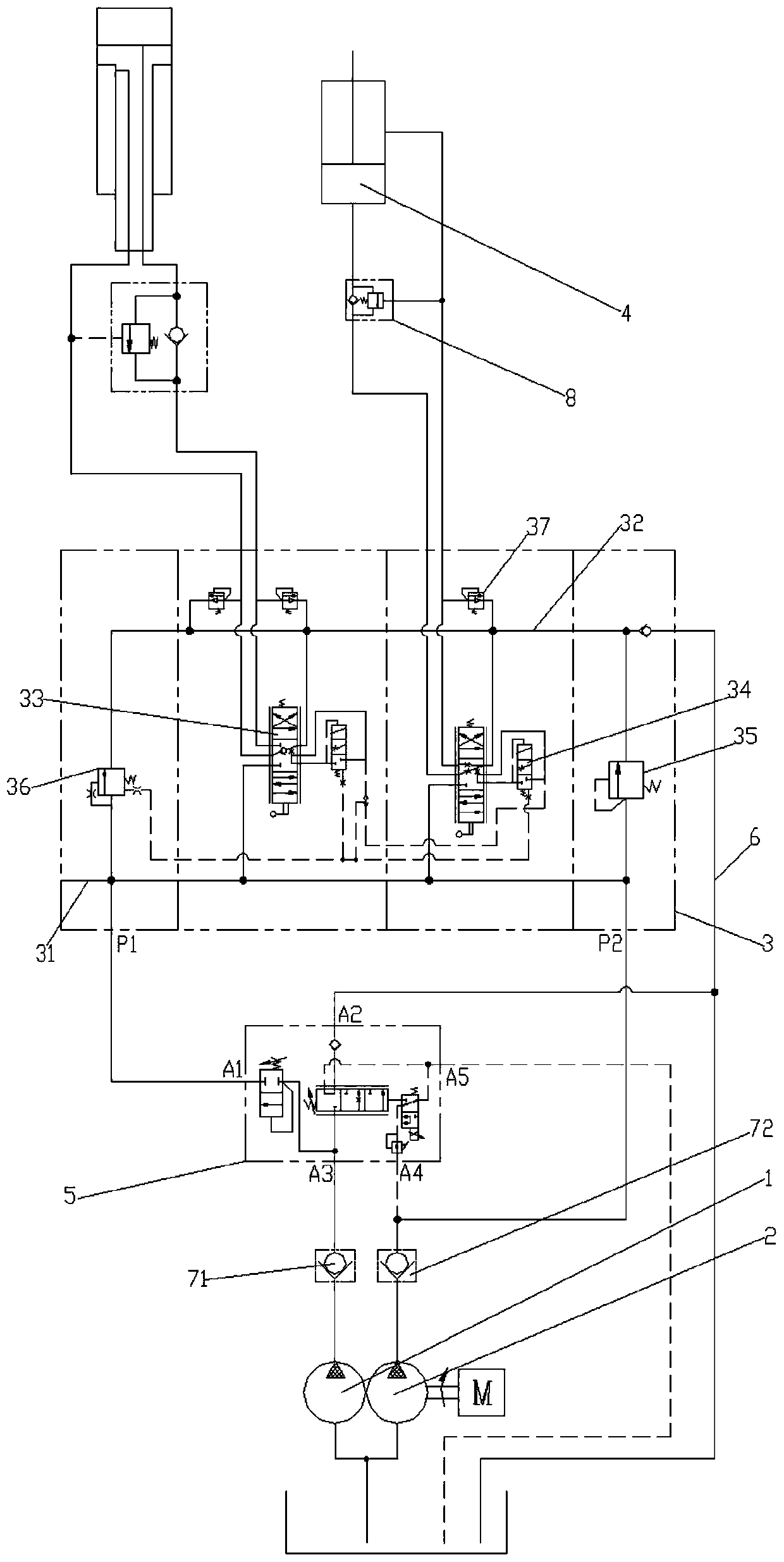
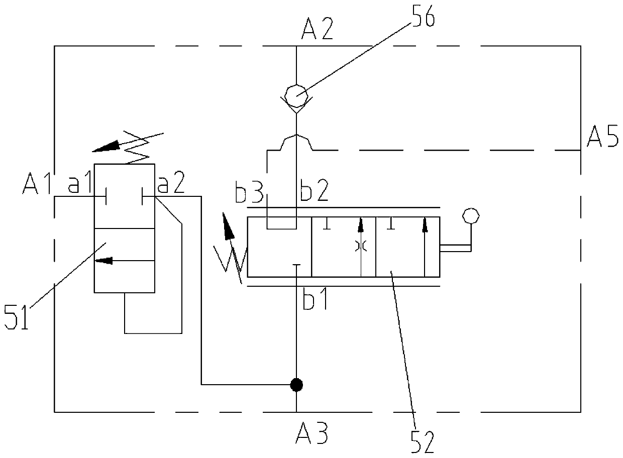
The invention relates to a crane hydraulic system and discloses a power control hydraulic system. The system involves a first constant flow pump, a second constant flow pump, an operating valve and aplurality of loading executing mechanisms, wherein the operating valve is connected with the loading executing mechanisms, and the first constant flow pump and the second constant flow pump are connected with an oil inlet of the operating valve so as to supply oil to all the loading executing mechanisms through the operating valve; and the system further involves a flow control valve, the flow control valve comprises a first oil outlet connected with the oil inlet of the operating valve, a second oil outlet connected with a main oil return oil way and a first oil inlet connected with the firstconstant flow pump, and the opening degree of the valve port of the second oil outlet of the flow control valve can be controlled so that flow input into the loading executing mechanisms can be adjusted. The invention further discloses a crane. According to the system and the crane, the power required by loading can be adjusted so that the requirements of various working conditions on the outputpower can be met.

Description

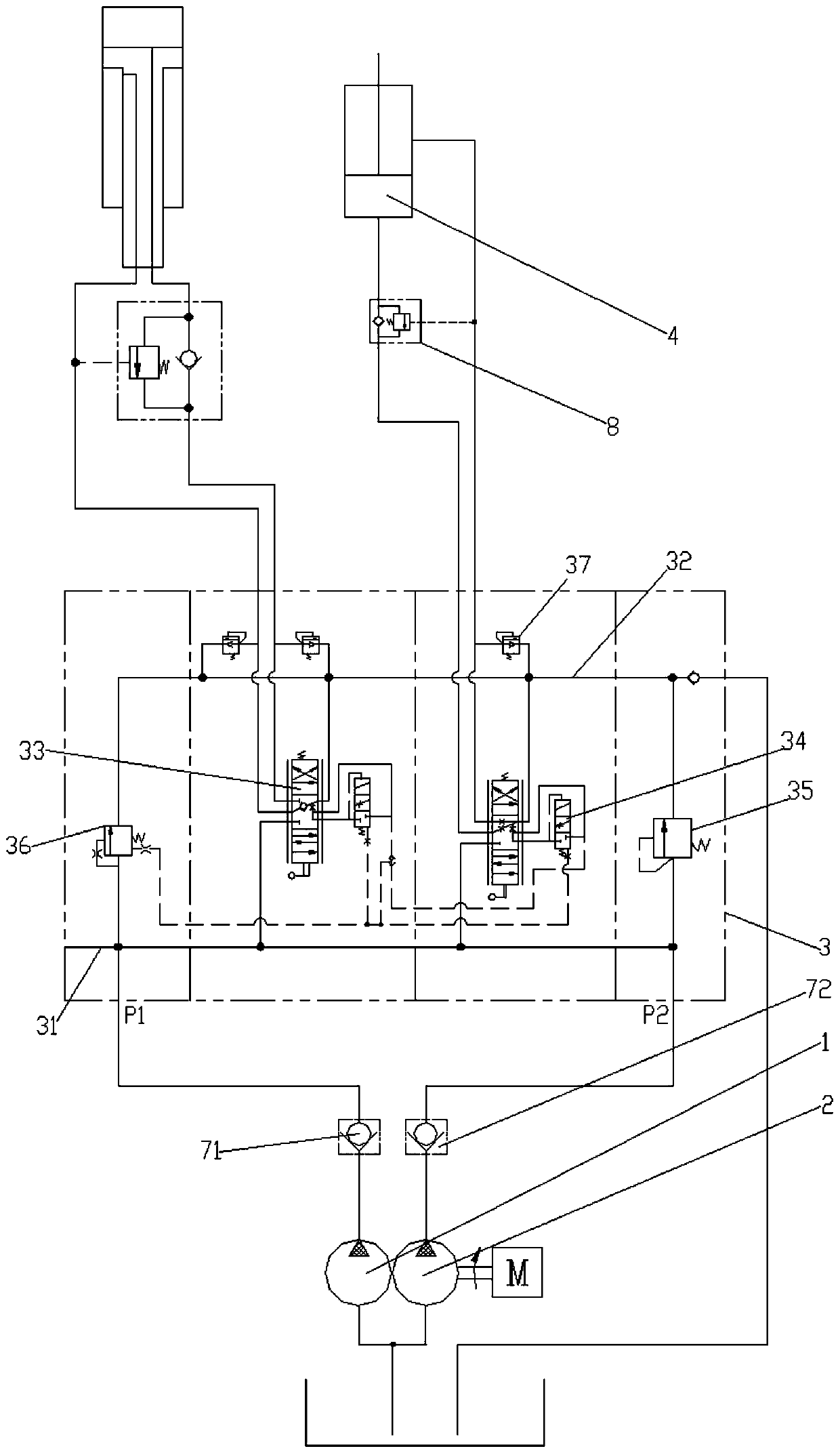
technical field [0001] The present invention relates to a crane hydraulic system, in particular to a power control hydraulic system, and also to a crane. Background technique [0002] The confluence hydraulic system of quantitative pumps for truck cranes is composed of multiple gear pumps, control valve groups and loads. The running speed of the main engine is improved through the confluence of multiple gear pumps. [0003] The gear pumps used in truck cranes are all fixed-displacement gear pumps. In order to improve the operating speed of the system, the double-pump confluence technology is often used. Double-pump confluence technology is a hydraulic system that combines the output flow of two pumps into one path before, on or after the control valve group, and then acts on the load together to increase the operating speed of the hydraulic system in a certain working condition. of a technique. [0004] specifically, figure 1 It shows a conventional double-pump confluence...

Claims


Application Information

Patent Timeline
IPC IPC(8): F15B11/08F15B13/04
CPCF15B11/08F15B13/04F15B2211/20538F15B2211/20576
Inventor 王磊周庆喜何伟黄珍谢娟萍
Owner ZOOMLION HEAVY IND CO LTD
Learn More