
Control method and control device for thermal management device of automobile, and storage medium

A control method and a technology for thermal management, which are applied in the fields of control methods for thermal management devices, storage media, and control devices, and can solve problems such as few operating modes and inability to meet user needs well.

Active Publication Date: 2020-04-03
GREE ELECTRIC APPLIANCES INC
View PDF6 Cites 2 Cited by
  • Summary
  • Abstract
  • Description
  • Claims
  • Application Information

AI Technical Summary

Problems solved by technology

[0005] The main purpose of this application is to provide a control method, control device, storage medium and processor for a thermal management device of an automobile, so as to solve the problem that the thermal management system in the prior art includes fewer operating modes and cannot better satisfy The question of user needs

Method used


Image

  • Control method and control device for thermal management device of automobile, and storage medium
  • Control method and control device for thermal management device of automobile, and storage medium
  • Control method and control device for thermal management device of automobile, and storage medium

Examples


Embodiment 1

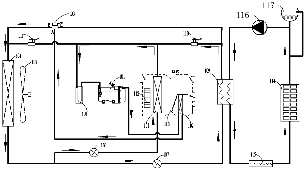
[0114] This embodiment relates to a thermal management device, image 3 and Figure 4 Schematic diagram of the structure of the thermal management device.

[0115] The device includes a vapor-liquid separator 100, a compressor 101, an inner condenser 102, an electromagnetic three-way valve 103, an outer heat exchanger 104, an outer fan 105, a first throttling element 106, a second throttling element 107, an inner evaporator 108, intermediate heat exchanger 109, first electromagnetic two-way valve 110, second electromagnetic two-way valve 111, blower 112, heating and cooling damper 113, battery pack heat exchange terminal 114, PTC electric heater 115, water pump 116 and expansion tank 117 , the specific connection relationship of each component is as follows image 3 and Figure 4 As shown, one end of the vapor-liquid separator 100 is connected to one end of the compressor 101, the other end of the compressor 101 is connected to one end of the inner condenser 102, and the ot...

Embodiment 3

[0135] This embodiment relates to a flow chart of the control method of the thermal management device in Embodiment 1, as shown in Figure 6 As shown, the method specifically includes:

[0136] ① Firstly, in S202, it is determined whether there is a defogging demand in the cabin. Generally, the defogging demand is formed by the driver setting the defogging mode through the operation panel;

[0137] If there is a need for demisting, enter step S203 to further determine whether the battery needs to be cooled:

[0138] If the battery needs to be cooled, go to S205 to judge the current outer ring condition. The judgment of the outer ring here is mainly to determine whether to use the cooling mode or the heating mode for the cabin defogging. The idea is: use cooling at medium and high temperatures (Tout≥M℃) Mode, that is to execute the third operation mode of S213: battery cooling + cabin cooling co-operation; at low temperature (Tout


PUM


Abstract

The invention provides a control method and device for a thermal management device of an automobile and a storage medium. The control method comprises the steps that an operation mode required by an automobile cabin is determined; an operation mode required by the battery is determined; and the thermal management device is controlled to enter a corresponding operation mode according to the operation mode required by the vehicle cabin and the operation mode required by the battery, wherein the method of controlling the thermal management device to enter the corresponding operation mode comprises at least controlling a cooling and heating air door to be in a full-cooling mode, a full-heating mode or a closing mode and controlling the water pump to be in an opening state or a closing state. The thermal management device is controlled to enter the corresponding operation mode according to the operation mode required by the vehicle cabin and the operation mode required by the battery, and eight operation modes including vehicle cabin refrigeration, battery cooling, vehicle cabin refrigeration+battery cooling, vehicle cabin heating, battery heating, vehicle cabin heating+battery heating,vehicle cabin heating defogging and battery cooling and vehicle cabin heating can be achieved.

Description

technical field [0001] The present application relates to the field of electric vehicles, and in particular, relates to a control method, a control device, and a storage medium of a thermal management device of a vehicle. Background technique [0002] Electric vehicles require good heat dissipation for their batteries and electronic control systems to maintain their optimum operating temperature. Therefore, electric vehicles are currently equipped with complex thermal management systems, especially those based on heat pump air conditioners, because of their high energy efficiency. , high system integration and other characteristics, has become the cutting-edge technology field of major OEM research. During the operation of the thermal management system, the requirements for passenger compartment cooling, battery cooling, passenger compartment cooling + battery cooling, battery heating, passenger compartment heating, passenger compartment windshield defrosting, battery heatin...

Claims


Application Information

Patent Timeline
Patent Type & Authority Applications(China)
IPC IPC(8): B60H1/00B60K1/00B60L58/26B60L58/27
CPCB60H1/00392B60H1/00642B60K1/00B60L58/26B60L58/27B60K2001/005B60K2001/008Y02T10/70
Inventor 李俊峰陈华英
Owner GREE ELECTRIC APPLIANCES INC
Learn More