A kind of harness threading equipment

A technology for pipe threading and equipment, applied in the field of pipe threading, can solve problems such as inconvenience in use, and achieve the effects of convenient use, strong practicability and saving processing costs.

Active Publication Date: 2021-02-12
西咸新区吉亚汽车部件有限公司
View PDF1 Cites 0 Cited by
  • Summary
  • Abstract
  • Description
  • Claims
  • Application Information

AI Technical Summary

Problems solved by technology

[0005] The existing technical solutions in the above patents have the following defects: after the wire harness is passed through the pipe, the wire harness needs to be extended into the PVC casing for a certain distance to connect with the wire harness of other equipment, and the above-mentioned wire harness is automatically inserted into the casing equipment after the wire harness is passed through the pipe , it is also necessary to cut the PVC sleeve, so that the wire harness protrudes out of the PVC sleeve, which is inconvenient to use

Method used


Image

  • A kind of harness threading equipment
  • A kind of harness threading equipment
  • A kind of harness threading equipment

Examples


Embodiment 1

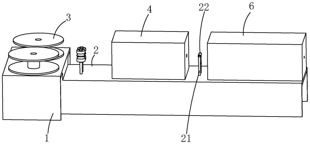
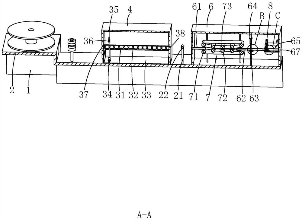
[0045] refer to figure 1 and figure 2 , is a wire harness threading device disclosed in the present invention, which includes a frame body 1 and a workbench 2 located on the frame body 1. On the surface of the workbench 2, two sets of winding posts 3 wound with wire harnesses are connected in rotation, and the winding posts 3 One side is provided with a lubrication box 4 on the workbench 2, refer to image 3 The side of the lubricating box 4 away from the winding post 3 is provided with a driving assembly 7 for driving the movement of the wire harness. There is a rotary column 22 which can be contacted with the wiring harness, and an annular wire groove is opened on the rotary column 22, and the annular wire groove is arranged along the circumferential direction of the rotary column 22, which is not shown in the figure.

[0046] refer to image 3 and Figure 4 The outer periphery of the drive assembly 7 is covered with a casing 6, and a first hollow wire tube 61 and a sec...

Embodiment 2

[0053] A method for using a wire harness threading device, comprising the following steps:

[0054]Step 1: Cut the casing. According to the requirements of the casing and the wiring harness, mark the casing with a measuring tool, then cut the casing with a cutting machine, and transfer the casing to a nearby installation by a transfer vehicle. hole 67;

[0055] Step 2: wiring harness lubrication, add lubricating oil to the oil tank 33, adjust the oil pump 34, the oil pump 34 pumps the lubricating oil in the oil tank 33 to the nozzle 36 through the pipeline 35, adjust the nozzle 36, spray the lubricating oil, and the lubricating oil passes through The flow hole 32 enters the third hollow wire tube 31 to lubricate the wiring harness in the third hollow wire tube 31;

[0056] Step 3: Initial installation of the wire harness, the end of the wire harness wound on the winding column 3 is inserted into the third hollow wire tube 31 through the wire inlet hole 37, and then passed thr...


PUM


Abstract

The invention relates to a wire harness threading device, which includes a frame body and a workbench. A winding column is rotatably connected to the surface of the workbench. A driving assembly is arranged on one side of the winding column. The first hollow wire tube and the second hollow wire tube are arranged on both sides of the casing, and a mounting hole is provided on the cover, and a hollow support tube is provided at the installation hole, and a shell is provided on the outer periphery of the hollow support tube, and a through hole is opened on the shell. hole, the second hollow wire tube, the through hole, the hollow support tube and the installation hole are arranged concentrically; The first air cylinder is connected on the handle portion of the knife. The wire harness threading equipment and its use method designed by the present invention realize the cutting of the wire harness, so that the wire harness protrudes out of the casing, which is convenient to use, and at the same time avoids the waste of the casing by secondary cutting of the casing, saves processing costs, and improves the production efficiency of the casing. Practical performance of wire harness through pipe equipment.

Description

technical field [0001] The invention relates to the field of pipe threading technology, in particular to a wire harness pipe threading device. Background technique [0002] Pipe threading is a processing method of threading wire bundles or tube bundles into plastic hoses or braided network pipes. It is mainly used in power supply, hardware, plastic, electronic appliances and other industries. If it is inserted into a plastic hose or a braided network pipe, the manpower consumption is serious and the time consumption is long. [0003] The Chinese patent with the notification number CN108400559A discloses a wire harness automatic threading sleeve equipment, its equipment base, and the sleeve automatic feeding and wire harness feeding part fixed on the equipment base, and the sleeve damage-free gripping part , wire harness penetration and finished product delivery integrated module part, the right side of the sleeve automatic feeding and wire harness feeding part is the wire h...

Claims


Application Information

Patent Timeline
Patent Type & Authority Patents(China)
IPC IPC(8): B21F11/00B26D3/16H02G1/08B23B5/16
CPCB21F11/00B23B5/167B26D3/16H02G1/08
Inventor 冯波何龙君
Owner 西咸新区吉亚汽车部件有限公司
Why Eureka
Try Eureka