
Process gas purging method

A process gas and process technology, applied in metal material coating process, electrical components, gaseous chemical plating, etc., can solve the problems of excessive particle size control, residual DCE in pipelines, short purge time, etc., and reduce the number of particles. , prolong the time, reduce the effect of process gas

Active Publication Date: 2020-03-31
BEIJING NAURA MICROELECTRONICS EQUIP CO LTD
View PDF7 Cites 4 Cited by
  • Summary
  • Abstract
  • Description
  • Claims
  • Application Information

AI Technical Summary

Problems solved by technology

[0004] However, in the above-mentioned method, when the purge stage is performed after the process, since the wafer is still in the chamber, the flow rate and time of feeding the gas will have an impact on the film thickness of the wafer, so the purge time is short and the gas The flow rate is low, and there will still be DCE residue in the pipeline, which will cause the particle size control after the process to exceed the standard

Method used


Image

  • Process gas purging method
  • Process gas purging method
  • Process gas purging method

Examples


Embodiment Construction

[0032] In order to enable those skilled in the art to better understand the technical solution of the present invention, the purging method provided by the present invention will be described in detail below in conjunction with the accompanying drawings.

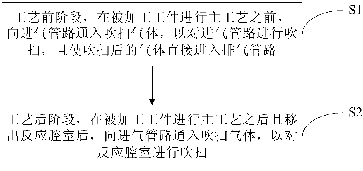
[0033] Such as figure 1 with figure 2 Shown, the purging method provided by the invention comprises the following steps:

[0034] S1, in the pre-process stage, before the main process of the processed workpiece, the purge gas is introduced into the intake pipeline 2 to purge the intake pipeline 2, and the purged gas directly enters the exhaust pipeline 4 ;

[0035] S2, in the post-process stage, after the processed workpiece undergoes the main process and is removed from the reaction chamber 3, a purge gas is introduced into the intake pipeline 2 to purge the intake pipeline 2 and the reaction chamber 3.

[0036] In this embodiment, the residual process gas in the intake pipeline 2 can be reduced by purging the intake pi...


PUM


Abstract

The invention provides a process gas purging method which comprises the following steps: in a pre-process stage, namely introducing purging gas into a gas inlet pipeline to purge the gas inlet pipeline before a processed workpiece is subjected to a main process, and enabling the purged gas to directly enter an exhaust pipeline; and in the post-process stage, after the processed workpiece is subjected to the main process and is moved out of a reaction chamber, introducing blowing gas into a gas inlet pipeline so as to blow the gas inlet pipeline and a reaction chamber. According to the processgas purging method provided by the invention, residual process gas in the gas inlet pipeline and the reaction chamber can be reduced, so that the number of particles on the processed workpiece afterthe processing process is reduced, and the standard of granularity control is met.

Description

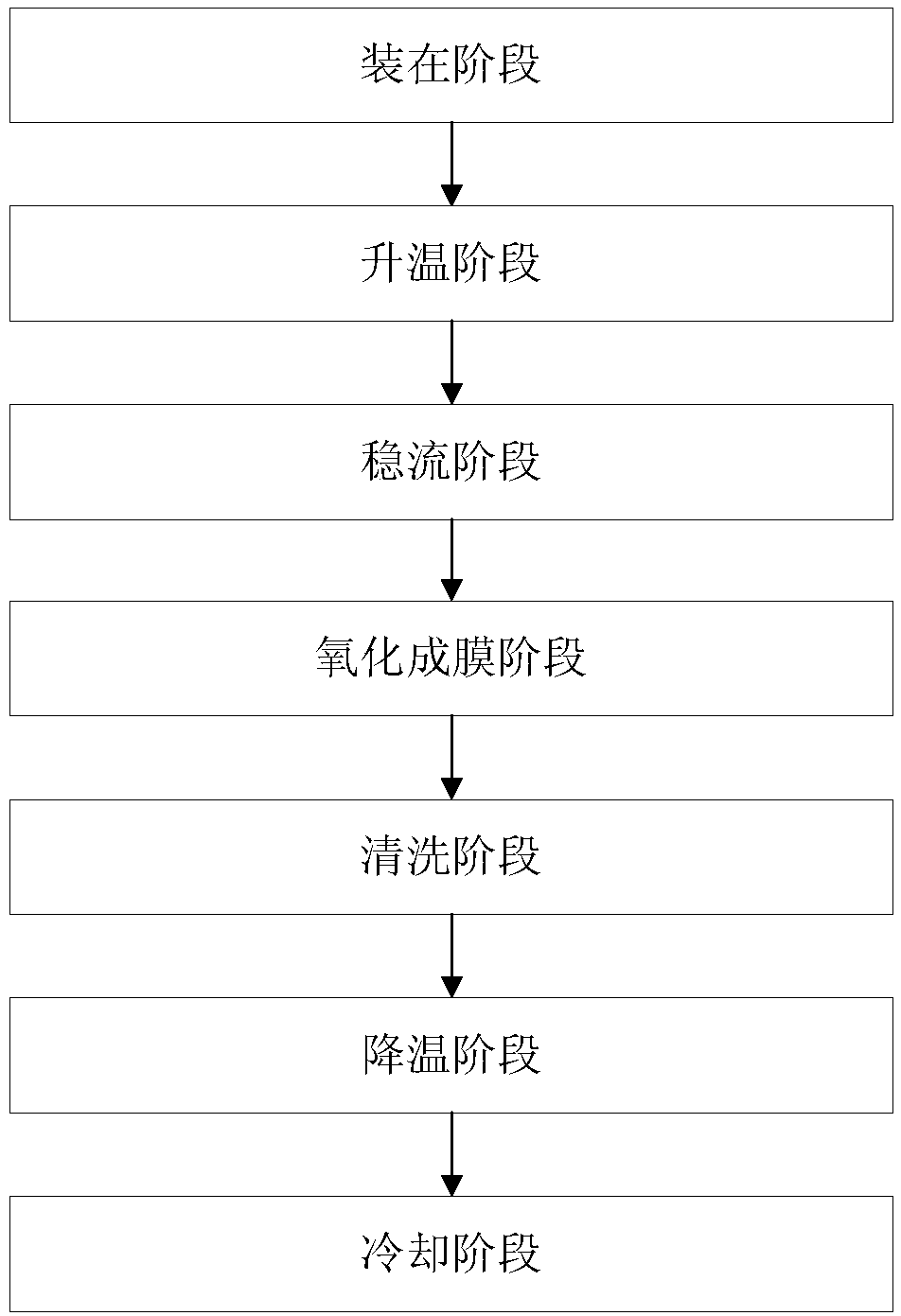
technical field [0001] The invention relates to the technical field of microelectronics manufacturing, in particular to a method for purging process gas. Background technique [0002] At present, in the field of microelectronics manufacturing technology, with the size of semiconductor devices getting smaller and smaller, the integration of chips is getting higher and higher, and the requirements for various process indicators are becoming more and more stringent. An important process index for inspecting film quality in the process, in the oxidation film forming process, DCE (C 2 h 2 CL 2 , Dichloroethylene) oxidation process can increase the growth rate of the oxide layer and improve the quality of the oxide layer, but due to its physical characteristics, it will affect the particle size control. [0003] In the prior art, the DCE oxidation process generally includes a loading stage (Load), an oxidation film forming stage (DCE Oxide), a cleaning stage (Purge) and a remov...

Claims


Application Information

Patent Timeline
Patent Type & Authority Applications(China)
IPC IPC(8): H01L21/67H01L21/02C23C16/455C23C16/40
CPCH01L21/67H01L21/02656H01L21/02661C23C16/455C23C16/40Y02P70/50
Inventor 林伟华魏明蕊吴艳华王玉霞
Owner BEIJING NAURA MICROELECTRONICS EQUIP CO LTD
Learn More