A centering strut and a loudspeaker with the same
A technology of centering struts and loudspeakers, which is applied in the field of electroacoustics, can solve the problems of high rigidity, fatigue and fracture failure of the conductive layer, etc., and achieve the effects of reducing structural rigidity, preventing failure risks, and simple production process
- Summary
- Abstract
- Description
- Claims
- Application Information
AI Technical Summary
Problems solved by technology
Method used
Image

Examples
Embodiment 1
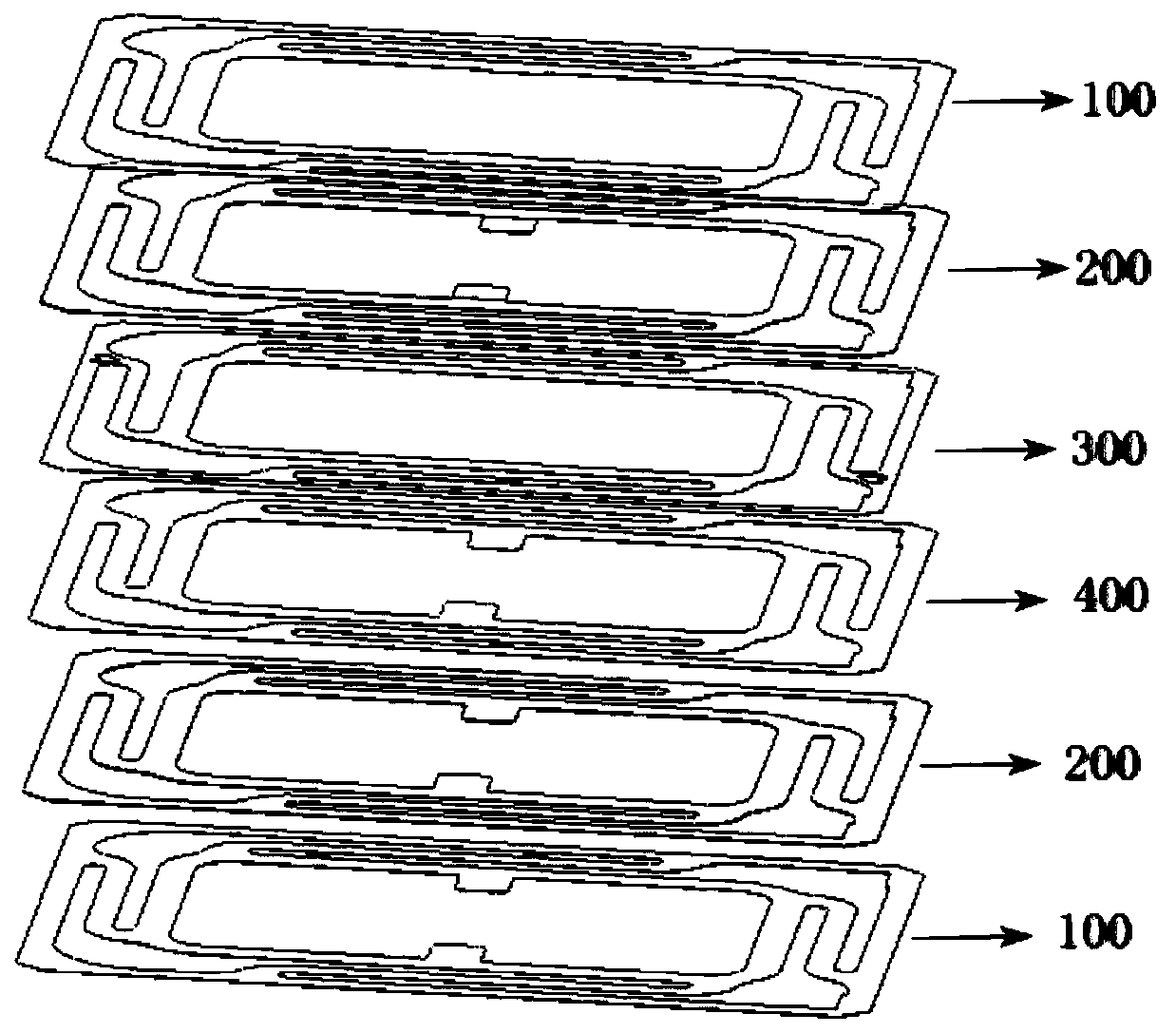
[0043] A centering strut, which adopts a multi-layer structure composed of multiple material layers or a multi-layer structure composed of multiple material layers and glue layers. The material layer includes a conductive layer located in the central area and a conductive layer located on the outer surface. The substrate layer, the substrate layer can be polyimide film (PI film), the conductive layer can be copper foil, and the copper foil is adhered to the polyimide film coated with adhesive by rolling process, or not Copper foil is produced directly on polyimide film using an adhesive.
[0044] The substrate layer is not limited to the above-mentioned polyimide film (PI film), and other polymer material films other than polyimide can also be selected, and the conductive layer is not limited to the above-mentioned copper foil, and can also be It is other metal layers or graphene conductive layers, etc.
[0045] Explain that the damper is a six-layer layered structure, such as ...
Embodiment 2
[0061] The same part as that of Embodiment 1 has been discussed in detail in Embodiment 1, and will not be repeated here. Compared with Embodiment 1, this embodiment is modified as follows:
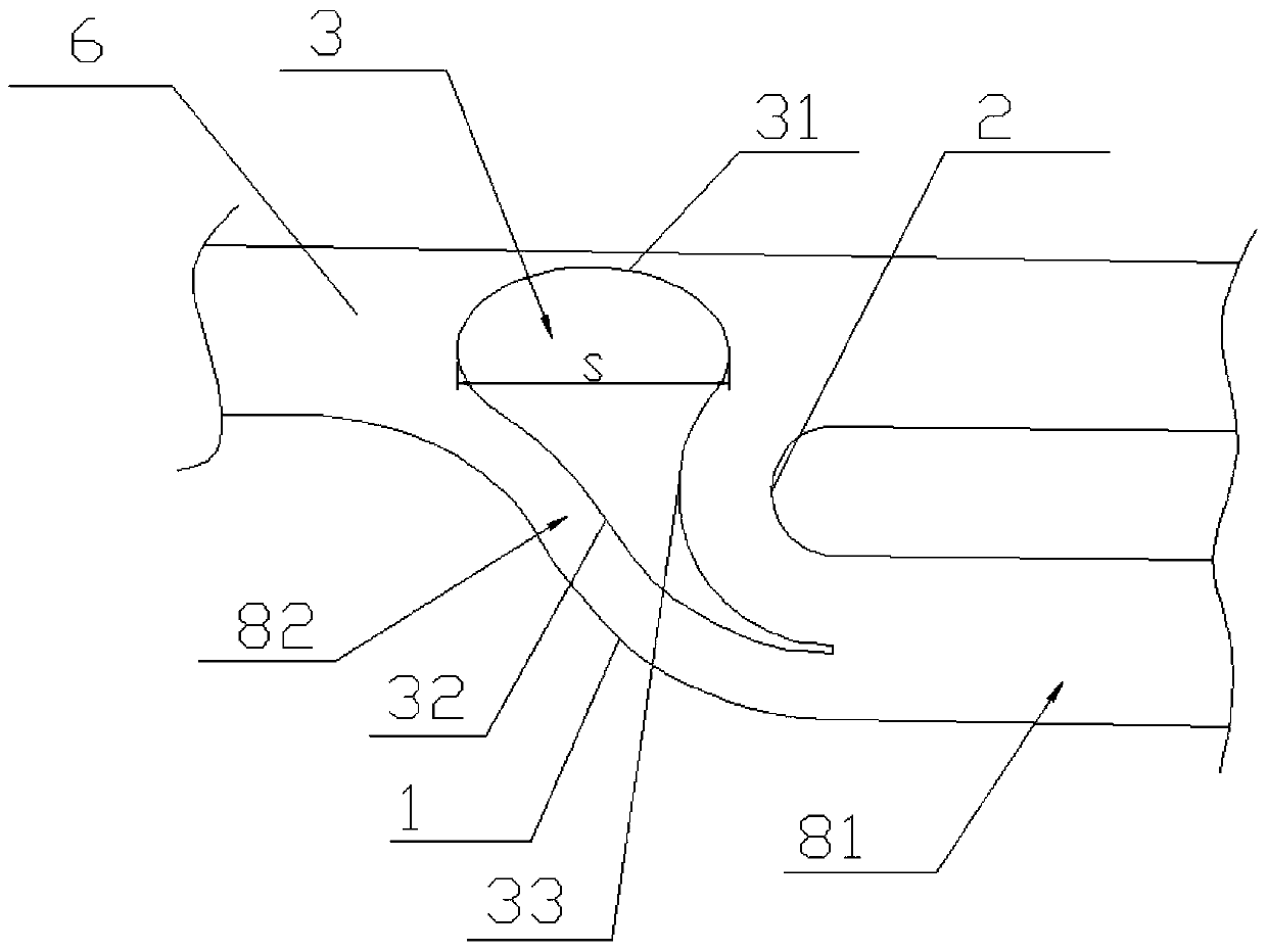
[0062] The shape of the hollow area 3 is an irregular geometric shape.
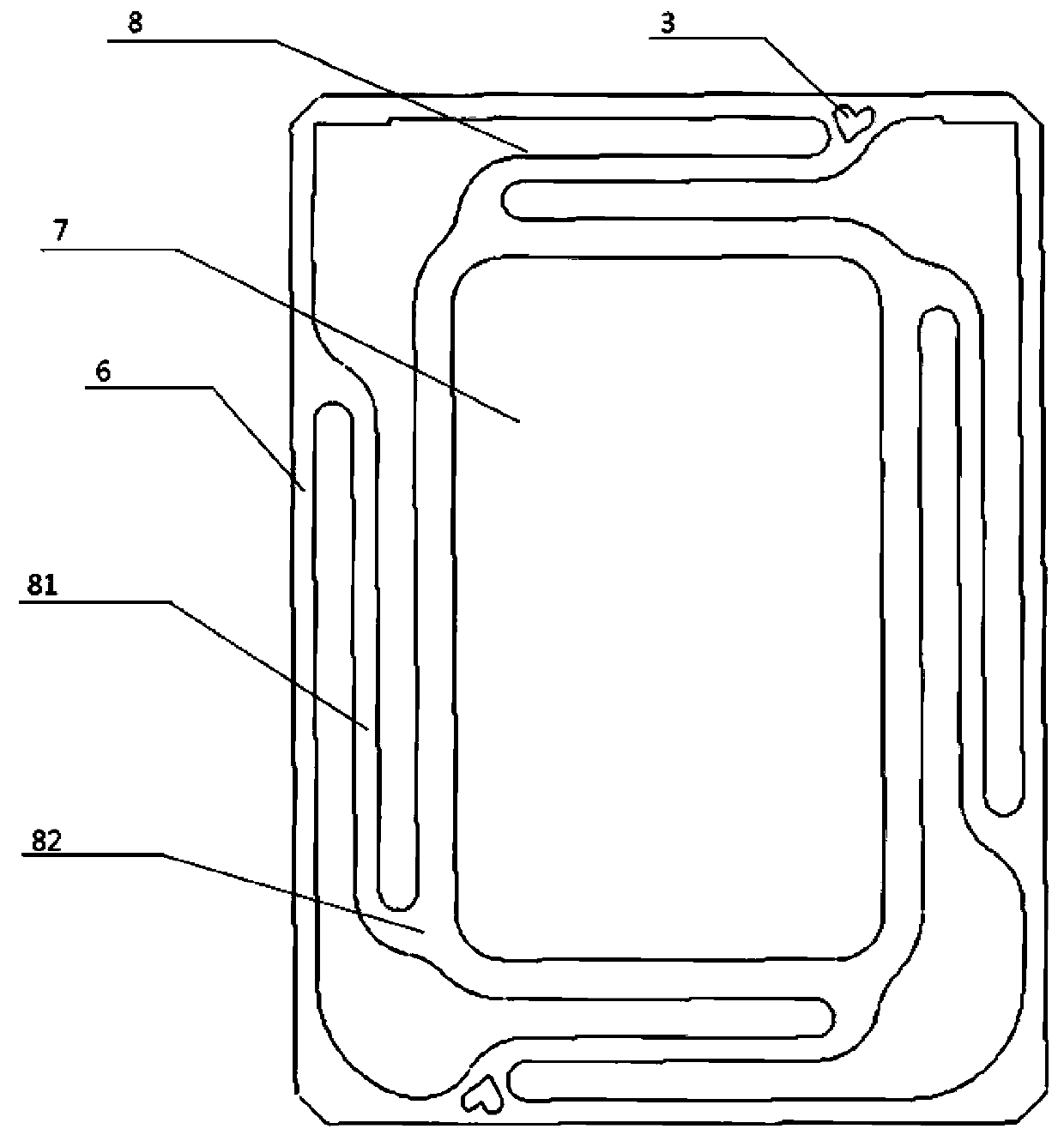
[0063] preferred, such as image 3 As shown, the root portion 82 of the conductive layer is provided with an outer arc edge portion 1 and an inner arc edge portion 2, the area between the outer arc edge portion 1 and the inner arc edge portion 2 is provided with a hollow area 3, and the outer arc edge portion 1 One end and one end of the inner arc edge portion 2 are both extended and connected to the cantilever body 81 , and the other end of the outer arc edge portion 1 and the other end of the inner arc edge portion 2 are both extended and connected to the first fixing portion 6 .
[0064] The hollow area 3 is surrounded by the first connecting edge portion 31, the second connecting edge portion 32 and the third co...
Embodiment 3
[0071] The same part as that of Embodiment 1 has been discussed in detail in Embodiment 1, and will not be repeated here. Compared with Embodiment 1, this embodiment is modified as follows:
[0072] The hollow area 3 is an irregular geometric shape.
[0073] preferred, such as image 3 As shown, the root portion 82 of the conductive layer is provided with an outer arc edge portion 1 and an inner arc edge portion 2, the area between the outer arc edge portion 1 and the inner arc edge portion 2 is provided with a hollow area 3, and the outer arc edge portion 1 One end and one end of the inner arc edge portion 2 are both extended and connected to the cantilever body 81 , and the other end of the outer arc edge portion 1 and the other end of the inner arc edge portion 2 are both extended and connected to the first fixing portion 6 .
[0074] The hollow area 3 is surrounded by the first connecting edge portion 31, the second connecting edge portion 32 and the third connecting edge...
PUM
 Abstract
Description
Claims
Application Information
 - R&D
- Intellectual Property
- Life Sciences
- Materials
- Tech Scout
- Unparalleled Data Quality
- Higher Quality Content
- 60% Fewer Hallucinations
Browse by: Latest US Patents, China's latest patents, Technical Efficacy Thesaurus, Application Domain, Technology Topic, Popular Technical Reports.
© 2025 PatSnap. All rights reserved.Legal|Privacy policy|Modern Slavery Act Transparency Statement|Sitemap|About US| Contact US: help@patsnap.com