Intelligent efficient sagger detection device based on visual system

A vision system and detection device technology, which is applied in the direction of measuring devices, optical testing of flaws/defects, and material analysis through optical means, can solve problems such as waste, misjudgment and missed judgment, and low efficiency, and achieve high efficiency. Working status, avoiding misjudgment and missed judgment, and the effect of high product qualification rate

Active Publication Date: 2020-03-27
BEIJING ZODNGOC AUTOMATIC TECH
View PDF6 Cites 1 Cited by
  • Summary
  • Abstract
  • Description
  • Claims
  • Application Information

AI Technical Summary

Problems solved by technology

[0003] 1. Because the broken sagger will affect the normal operation of the sagger conveying stick, and will also stay in the furnace of the electronic kiln, thus causing the operation failure of the electronic kiln
[0004] 2. Due to the broken sagger, the electronic powder material previously loaded into the sagger cannot be led out of the furnace, which will cause waste on the one hand, and cause operational failure of the electronic kiln on the other hand
[0005] 3. The electronic powder material accumulated in the furnace due to the fragmentation of the sagger is clear and troublesome, so it is very intensive for workers to clean the furnace, and it is difficult to obtain the desired cleaning effect
[0006] At present, the detection of the appearance of saggers in the use of roller furnaces in China mainly relies on artificial eyes to observe the appearance of saggers. The ambient temperature around the roller furnaces is high and operates 24 hours a day, relying solely on manual labor for a long time at high temperature To detect whether the sagger is good or bad in the environment, it is easy to cause misjudgment and missed judgment, and the cost is high, the efficiency is low, and it is easy to cause the generation of defective products and the waste of materials

Method used


Image

  • Intelligent efficient sagger detection device based on visual system
  • Intelligent efficient sagger detection device based on visual system
  • Intelligent efficient sagger detection device based on visual system

Examples


Embodiment Construction

[0037] In order to make the object, technical solution and advantages of the present invention clearer, the present invention will be further described in detail below in conjunction with the accompanying drawings and embodiments. It should be understood that the specific embodiments described here are only used to explain the present invention, not to limit the present invention.

[0038] It should be understood that the orientations or positional relationships indicated by the terms "top", "middle", "upper", "side", "inner", "left side", "right side" etc. are based on those shown in the accompanying drawings. Orientation or positional relationship is only for the convenience of describing the present invention and simplifying the description, and does not indicate or imply that the referred device or element must have a specific orientation, be constructed and operated in a specific orientation, and thus should not be construed as a limitation of the present invention.

[00...


PUM


Abstract

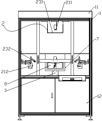
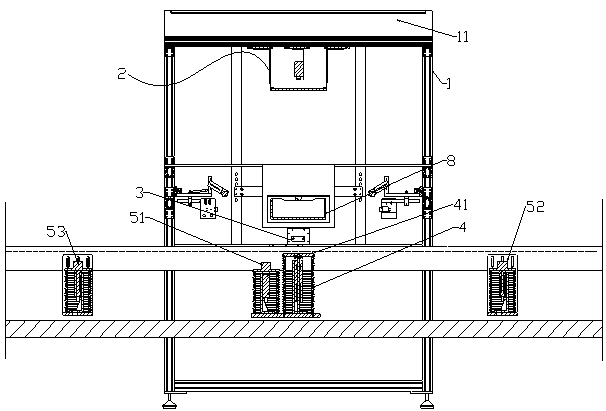
The invention relates to an intelligent efficient sagger detection visual system based on a visual system. The intelligent efficient sagger detection visual system comprises: a supporting frame, wherein a fresh air system installed in the supporting frame, and a visual system used for sagger image detection, wherein the visual system comprises an industrial camera and an image processing unit, theimage processing unit is used for processing images obtained by the industrial camera, and the industrial camera is installed on the top face and the side face in the supporting frame; and comprisesan alignment assembly which is used for alignment during sagger detection, is a first air cylinder and locates right under the industrial camera at the top, a lifting air cylinder assembly used for lifting during sagger detection, and an intercepting assembly which is used for intercepting saggers on a kiln rotation line and comprises an external intercepting air cylinder and an internal intercepting air cylinder, wherein the external intercepting air cylinder is used for intercepting to-be-detected saggers which do not enter the detection device, and the internal intercepting air cylinder isused for intercepting the to-be-detected saggers in the detection device. According to the invention, 24-hour intelligent detection and automatic identification can be realized, the detection precision is high, the product qualification rate is high, and the productivity is high.

Description

technical field [0001] The invention relates to an intelligent and efficient sagger detection device based on a vision system, belonging to the technical field of lithium-ion battery production equipment. Background technique [0002] In the production process of lithium-ion battery positive electrode materials, when the electronic kiln sinters the electronic powder material, it needs to put the electronic powder into the sagger, and the sagger and the electronic powder material enter the electronic kiln for firing. The sagger carries the electronic powder material out of the kiln together. The electronic powder material in the sagger is disintegrated at the crushing station, and then poured out of the sagger. After the electronic powder material is poured out, the empty sagger is cleaned. After the station is cleaned, it enters the charging station for charging, and then it is re-introduced into the electronic kiln for firing. It can be seen from this that the sagger is a ...

Claims


Application Information

Patent Timeline
IPC IPC(8): G01N21/01G01N21/95
CPCG01N21/01G01N21/95
Inventor 王秘梁长国冯龙申程晓强黑海群朱超平
Owner BEIJING ZODNGOC AUTOMATIC TECH
Why Eureka
Try Eureka