
Improved bar straightness detection system and method based on visual detection

A detection system and visual detection technology, applied in the field of bar rolling, can solve the problems of difficulty in bar straightness detection, easy error, and unstable bar running process.

Inactive Publication Date: 2020-03-27
TAIYUAN UNIVERSITY OF SCIENCE AND TECHNOLOGY +1
View PDF4 Cites 2 Cited by
  • Summary
  • Abstract
  • Description
  • Claims
  • Application Information

AI Technical Summary

Problems solved by technology

[0003] Patent application CN201910342689.9 provides a bar straightness detection system and detection method. Due to the complexity of the actual situation, the running process of the bar is not stable, which brings difficulties to the straightness detection of the bar and is prone to errors

Method used


Image

  • Improved bar straightness detection system and method based on visual detection
  • Improved bar straightness detection system and method based on visual detection

Examples


Embodiment Construction

[0035] The objects and functions of the present invention and methods for achieving the objects and functions will be clarified by referring to the exemplary embodiments. However, the present invention is not limited to the exemplary embodiments disclosed below; it can be implemented in various forms. The essence of the description is only to help those skilled in the relevant art comprehensively understand the specific details of the present invention. Hereinafter, embodiments of the present invention will be described with reference to the accompanying drawings. In the drawings, the same reference numerals represent the same or similar components, or the same or similar steps.

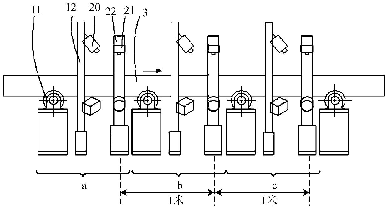
[0036] In the following, an improved visual detection-based bar straightness detection system provided by the present invention will be described through specific examples, as figure 1 The schematic diagram of the layout of an improved bar straightness detection system based on visual inspection is...


PUM


Abstract

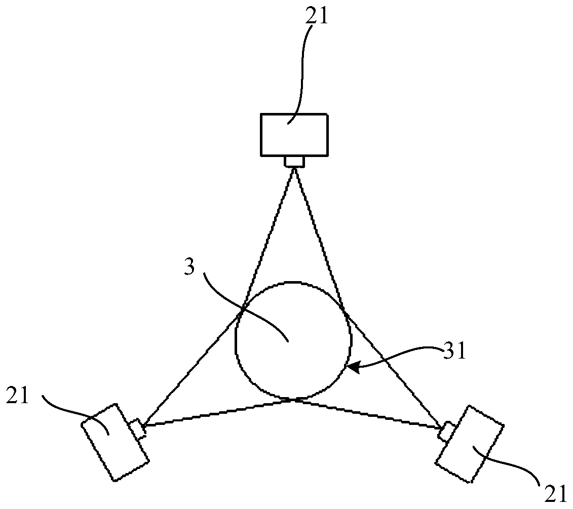
The invention provides an improved bar straightness detection system based on visual detection. The improved bar straightness detection system comprises three sets of straightness detection devices. The straightness detection device comprises a first annular rack and a second annular rack; three lasers are evenly distributed on the first annular rack, when a bar moves to the first annular rack where the lasers are distributed, lasers emitted by the three lasers surround the circumference of the bar to form a circular ring, and three CCD cameras are evenly distributed on the second annular rack. The distance between every two adjacent sets of straightness detection devices is 1 m, and the three CCD cameras of each set of straightness detection devices shoot three circular ring images formedaround the bar at the same time. Aiming at the problem that the operation process of the bar is not stable, three groups of pictures are shot at the same time, and errors caused by vibration of the bar are avoided in the continuous detection process.

Description

technical field [0001] The invention relates to the technical field of bar rolling, in particular to an improved visual inspection-based bar straightness detection system and method. Background technique [0002] At present, the methods for measuring straightness at home and abroad mainly include: 1) laser collimation method; 2) self-collimation light tube detection method; 3) wire drawing method; 4) coordinate measurement method, etc. The first two methods use laser light and white light as the straight line reference respectively, and measure the straightness error according to the point-by-point movement of the target or reflector in the direction of the measured line; the third method uses the tensioned wire (such as thin steel wire) as the straight line reference, Use appropriate means (such as capacitance, inductance) to measure the straightness error. The above measurement methods are only suitable for offline sampling inspection, and cannot be used for online real-t...

Claims


Application Information

Patent Timeline
IPC IPC(8): G01B11/27G06T7/00G06T7/13G06T7/62
CPCG01B11/272G06T7/0004G06T2207/10004G06T2207/30108G06T7/13G06T7/62
Inventor 马立东梁苏苏仝浩源静大海马立峰王荣军孟进礼
Owner TAIYUAN UNIVERSITY OF SCIENCE AND TECHNOLOGY
Learn More