


Quick Research
Generate reliable direction feasibility study reports for your R&D in just a few steps.

Technical Q&A
Discover and master advanced knowledge NOW. Basics, ideas, possibilities, all at once.

Find Solutions
As an expert in R&D theories, this can generate solutions to your technical problems instantly.

Evaluate Feasibility
Analyze your overall solution with one click, know your potential R&D risks in advance.

Monitor Landscape
Get weekly tech updates, stay abreast of the latest tech innovations and key insights.
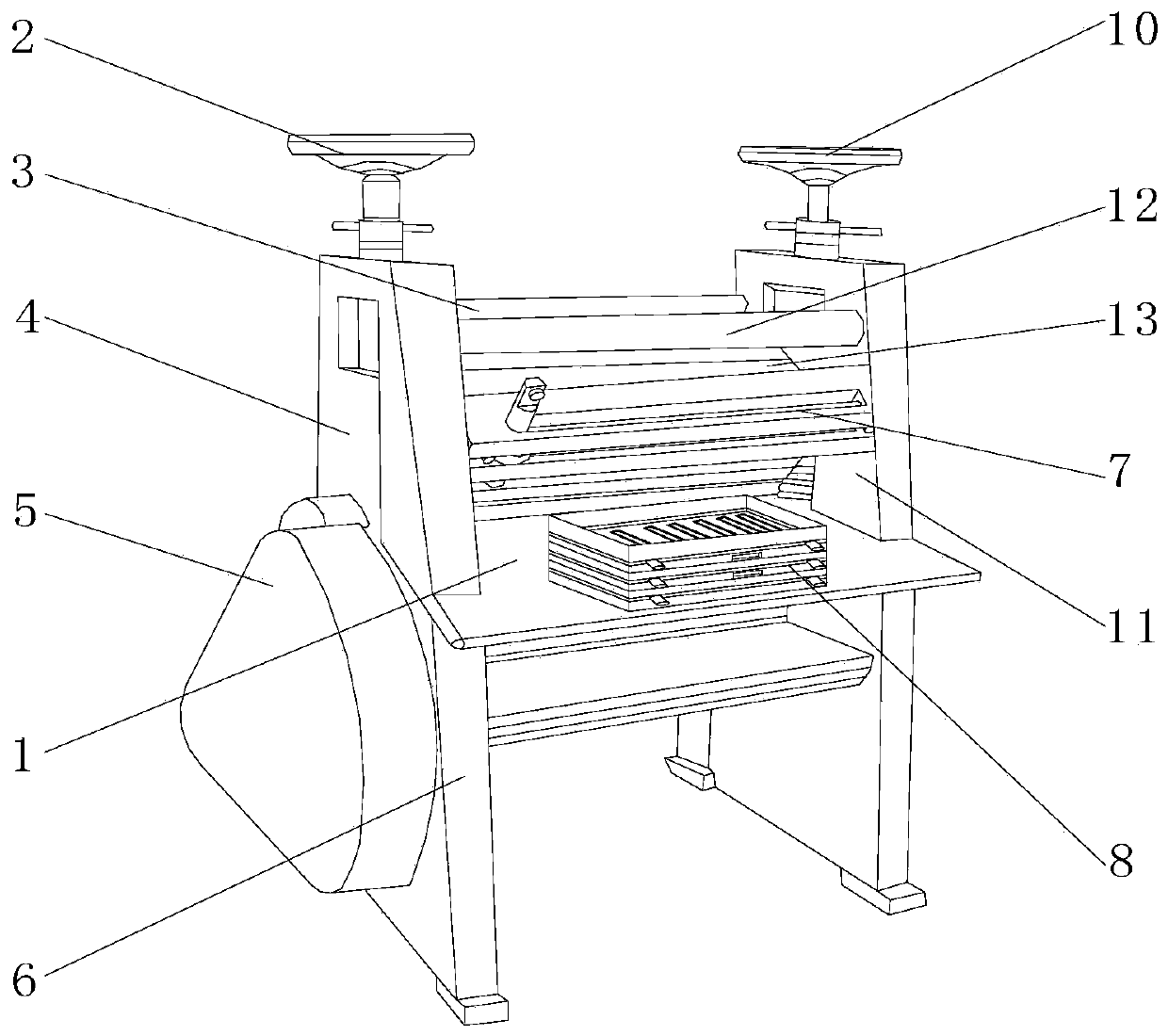
Press polishing device applied to production of textile fabric
A technology of textile fabrics and light devices, which is applied in the cutting of textile materials, dumping of textile materials, textiles and papermaking, etc., can solve the problems of affecting the next use, reducing the use efficiency of devices, and the cloth is easy to breed toxins, etc., to achieve convenience Dustproof protection, increase service life, increase the effect of calendering effect
- Summary
- Abstract
- Description
- Claims
- Application Information
AI Technical Summary
Problems solved by technology
Method used
Image

Examples
Embodiment 1
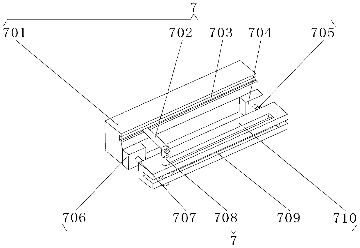
[0029] Embodiment one: if image 3 , 4As shown, the movable cloth cutting mechanism 7 includes a fixed seat 701, a cutting blade 702, a cutting groove 703, a positioning block 704, a No. 1 screw rod 705, a positioning seat 706, a No. 2 screw rod 707, an adjustment slider 708, a sliding Road 709, sliding seat 710, positioning seat 706, cutting groove 703 and positioning block 704 are located at the front end of fixing seat 701, cutting groove 703 is located at the upper end of positioning seat 706, and positioning block 704 is located at one side of positioning seat 706. The screw rod 707 is positioned at the front end of the positioning seat 706, the No. 1 screw rod 705 is positioned at the front end of the positioning block 704, the slide seat 710 is positioned at the front end of the No. In the inside of the road 709, a welding seat is arranged between the positioning seat 706, the positioning block 704 and the fixed seat 701, and the rear ends of the positioning seat 706 a...
Embodiment 2
[0030] Embodiment two: if Figure 5 , 6 As shown, the layered cooling box storage mechanism 8 includes a bottom shelf 801, a top shelf 802, a middle shelf 803, a cooling plate 804, a liquid inlet pipe 805, a water cooling pipe 806, a pull groove 807, a liquid outlet pipe 808, a middle shelf The rack 803 is located at the upper end of the bottom rack 801, the top rack 802 is located at the upper end of the middle rack 803, the cooling plate 804 is located inside the top rack 802, the water cooling tube 806 is located inside the cooling plate 804, and the liquid inlet pipe 805 is connected to the outlet pipe 805. The liquid pipe 808 is positioned at the front end of the cooling plate 804, the liquid outlet pipe 808 is positioned at one side of the liquid inlet pipe 805, the draw groove 807 is positioned at the front end of the top shelf 802, a hinge is arranged between the bottom shelf 801 and the middle shelf 803, and the bottom shelf The upper end of the rack 801 is flexibly ...
Embodiment 3
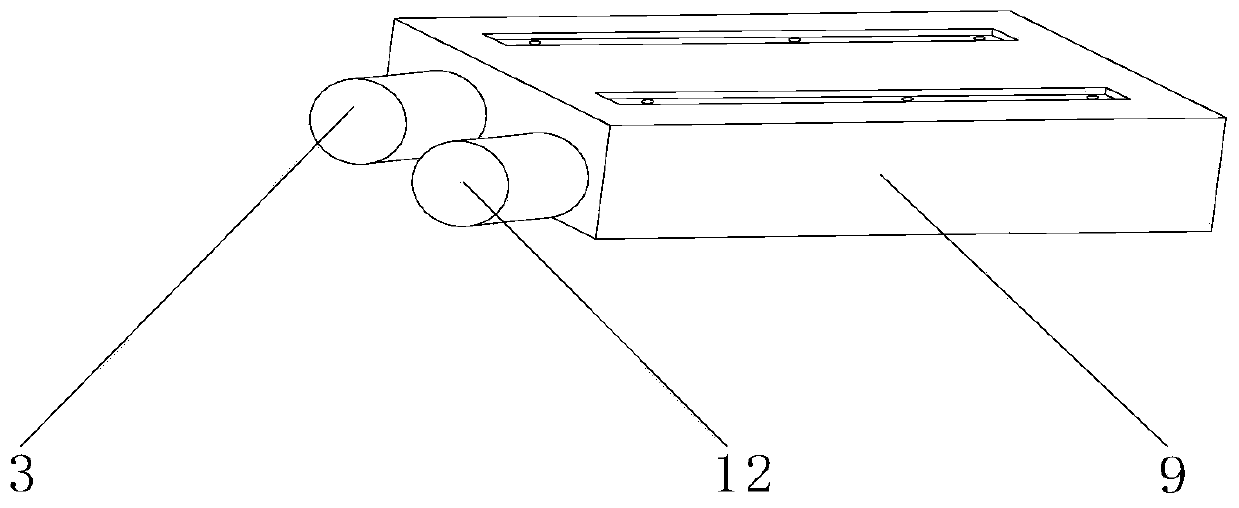
[0031] Embodiment three: as figure 2 , 7 As shown, the in-line protective cover mechanism 9 includes a dustproof protective cover 901, a No. 1 positioning slot 902, a No. 2 positioning slot 903, a No. 1 additional slot 904, a drip irrigation hole 905, a No. 2 additional slot 906, and a No. 1 positioning slot 902. The No. 2 positioning slot 903 is located inside the dustproof protective cover 901, the No. 2 positioning slot 903 is located on one side of the No. 1 positioning slot 902, and the No. 1 additional slot 904 and No. 2 additional slot 906 are located at the upper end of the dustproof protective cover 901. The No. 2 addition slot 906 is located on one side of the No. 1 addition slot 904, the drip irrigation hole 905 is located inside the No. 2 addition slot 906, and a fixed slot is arranged between the dustproof protective cover 901, the No. 1 positioning slot 902, and the No. 2 positioning slot 903. , the inside of the dustproof protective cover 901 is fixedly connec...
PUM
 Abstract
Description
Claims
Application Information
 - R&D Engineer
- R&D Manager
- IP Professional
- Industry Leading Data Capabilities
- Powerful AI technology
- Patent DNA Extraction
Browse by: Latest US Patents, China's latest patents, Technical Efficacy Thesaurus, Application Domain, Technology Topic, Popular Technical Reports.
© 2024 PatSnap. All rights reserved.Legal|Privacy policy|Modern Slavery Act Transparency Statement|Sitemap|About US| Contact US: help@patsnap.com