
Rapid dyeing device for textile production

A rapid dyeing and textile technology, applied in textiles and papermaking, textile material processing, and textile material processing equipment configuration, etc. Effect

Active Publication Date: 2020-03-27
HANGZHOU XINLONG PRINTING AMD DYEING CO LTD
View PDF6 Cites 4 Cited by
  • Summary
  • Abstract
  • Description
  • Claims
  • Application Information

AI Technical Summary

Problems solved by technology

[0003] In textile production, it is necessary to dye gauze, which requires the use of dyeing devices. However, when the traditional dyeing device dyes gauze, it arranges the traveling distance of the gauze in the dyeing pool, but this kind of dyeing takes a long time. Only the dyeing pool can fully soak the gauze, which not only takes up a lot of space, but also wastes dye

Method used


Image

  • Rapid dyeing device for textile production
  • Rapid dyeing device for textile production
  • Rapid dyeing device for textile production

Examples


Embodiment 1

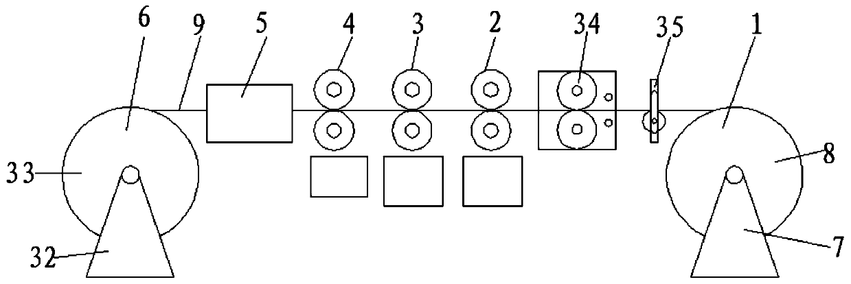
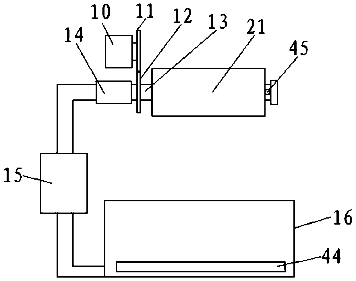
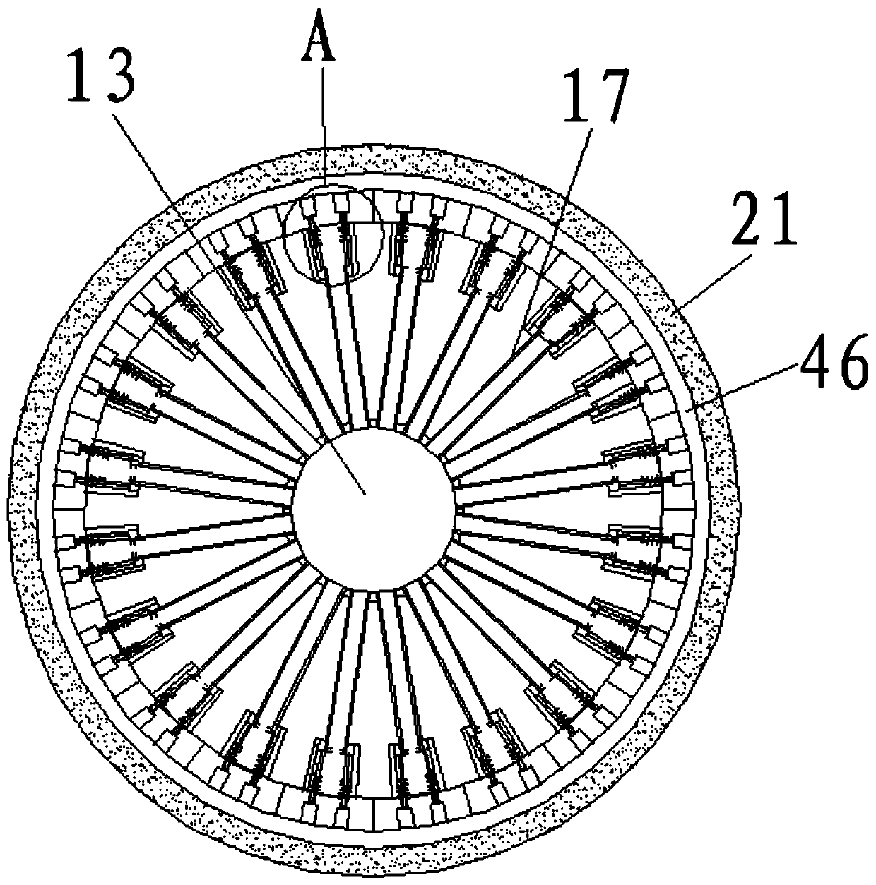
[0034] See Figure 1-9 , According to an embodiment of the present invention, a rapid dyeing device for textile production includes a cloth rolling mechanism 1, a first dyeing mechanism 2, a second dyeing mechanism 3, a scraping mechanism 4, a drying mechanism 5 and a winding mechanism 6 , The cloth rolling mechanism 1 includes a first base 7, a cloth rolling drum 8 is connected between the first bases 7 through a first movable shaft, and a cloth 9 is crimped on the cloth rolling drum 8. Pass through the first dyeing mechanism 2, the second dyeing mechanism 3, the scraping mechanism 4, and the drying mechanism 5 in sequence, and are crimped by the winding mechanism 6, the first dyeing mechanism 2 and the second dyeing mechanism 3 each includes two motors 10, the output end of the motor 10 is provided with a first gear 11, one side of the first gear 11 is meshed with a second gear 12, and the second gear 12 is fixed sleeve Set on the middle tube 13, the middle tube 13 is a tube...

Embodiment 2

[0037] See Figure 1-9 For the first dyeing mechanism 2, a dust removing mechanism 34 and a pulling mechanism 35 are provided between the first dyeing mechanism 2 and the cloth rolling mechanism 1. The dust removal mechanism 34 includes a housing, two ends of the housing are provided with cloth channels, two active rotating rollers 36 are arranged between the housings, and a cleaning brush is fixed on the active rotating roller 36. 37. One side of the cleaning brush 37 is located on the housing with a plurality of dust suction ports 38, and the dust suction ports 38 are connected with the input end of the vacuum cleaner 39. The lifting mechanism 35 includes two side plate racks 40. The side plate racks 40 are provided with notches. A passive roller 41 is arranged between the notches. The two ends of the passive roller 41 are located A first bearing is sleeved between the side plate frames 40, a bracket 42 is fixed on the first bearing, a screw rod 43 is connected to the bracke...


PUM


Abstract

The invention discloses a rapid dyeing device for textile production. The rapid dyeing device comprises a cloth rolling mechanism, a first dyeing mechanism, a second dyeing mechanism and a scraping mechanism, a drying mechanism and winding mechanism, wherein the cloth rolling mechanism comprises first bases; a cloth rolling cylinder is connected between the first bases through a first movable shaft; the cloth rolling cylinder is wound with cloth; the cloth sequentially penetrates through the first dyeing mechanism, the second dyeing mechanism, the scraping mechanism and the drying mechanism and is wound by the winding mechanism; each of the first dying mechanism and the second dyeing mechanism comprises two motors; the output end of each motor is provided with a first gear; one side of thefirst gear is meshed with a second gear; the second gear is fixedly arranged on a middle tube in a sleeving mode, and the middle tube is a tube sealed at one end; and one end of the middle tube is connected with a water pump through a rotary connecting piece. The rapid dyeing device has the beneficial effects that the dyeing speed is high, the dyeing quality can be ensured, and the required spacefor dye and dyeing can be effectively saved.

Description

Technical field [0001] The invention relates to the field of textile dyeing, in particular to a rapid dyeing device for textile production. Background technique [0002] The original intent of textile is taken from the general term of spinning and weaving, but with the continuous development and improvement of the textile knowledge system and discipline system, especially after the production of non-woven textile materials and three-dimensional composite weaving technologies, the current textile is not only traditional Hand-spinning and weaving also include non-woven technology, modern three-dimensional weaving technology, modern electrostatic nano-web technology and other textiles for clothing, industrial use, and decoration. Therefore, modern textile refers to a fiber or a collection of fibers Body's multi-scale structure processing technology. [0003] In textile production, the gauze needs to be dyed, which requires the use of a dyeing device. However, when the traditional dye...

Claims


Application Information

Patent Timeline
Patent Type & Authority Applications(China)
IPC IPC(8): D06B1/16D06B15/02D06B23/04D06B23/20D06G1/00
CPCD06B1/16D06B15/02D06B23/20D06G1/00D06B23/04Y02P70/62
Inventor 倪卫荣
Owner HANGZHOU XINLONG PRINTING AMD DYEING CO LTD
Learn More