Machining center clamp and machining center

A fixture and jaw technology, which is applied in the field of processing machine tools, can solve the problems of relative movement between the workpiece and the fixture, slow clamping speed of the fixture, and reduced machining accuracy, and achieve the effects of convenient tool setting, improved machining efficiency, and high machining accuracy

Inactive Publication Date: 2020-03-27
淄博海纳百川机械有限公司
View PDF0 Cites 0 Cited by
  • Summary
  • Abstract
  • Description
  • Claims
  • Application Information

AI Technical Summary

Problems solved by technology

The clamping speed of the fixture in the existing machining center is relatively slow, and due to the force between the tool and the workpiece during the machining process, it is easy to cause relative movement between the workpiece and the fixture, resulting in reduced machining accuracy

Method used


Image

  • Machining center clamp and machining center
  • Machining center clamp and machining center
  • Machining center clamp and machining center

Examples


Embodiment Construction

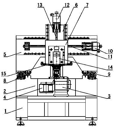
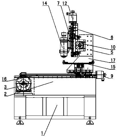
[0024] Figure 1~9 It is the best embodiment of the present invention, below in conjunction with attached Figure 1~9 The present invention will be further described.

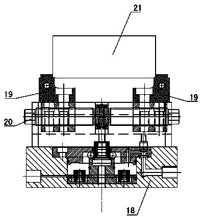
[0025] A clamp for a machining center, including a clamp base 18, clamp jaws 19 and clamp screw 20, two clamp jaws 19 are arranged symmetrically on both sides of the clamp base 18, and the clamp jaws 19 are slidably installed on the upper side of the clamp base 18 , the inner side of the upper part of each jaw 19 is provided with a relief port, thereby forming a loading part on the upper part of the jaw 19, the jaw screw 20 is rotatably installed on the clamp base 18, and the two ends of the jaw screw 20 are respectively connected to The jaws 19 on the corresponding side are threaded, and the jaw screw 20 is connected with a clamping power device that drives it to rotate. The jaw lead screw 20 of the fixture of this machining center simultaneously drives the two jaws 19 to move in opposite directions synchron...


PUM


Abstract

The invention discloses a machining center clamp and a machining center, which belong to the technical field of machining machine tools. The machining center clamp is characterized in that two clamping jaws (19) are symmetrically arranged on the two sides of a clamp base (18), the clamping jaw (19) is mounted on the upper side of the clamp base (18) in a sliding manner; a receding opening is formed in the inner side of the upper portion of each clamping jaw (19), so that a carrying part is formed on the upper portion of each clamping jaw (19); a clamping jaw lead screw (20) is rotationally installed on the clamp base (18), the two ends of the clamping jaw lead screw (20) are in threaded connection with the clamping jaws (19) on the corresponding sides respectively, and the clamping jaw lead screw (20) is connected with a clamping power device for driving the clamping jaw lead screw to rotate. According to the machining center clamp disclosed in the invention, a workpiece is firmly clamped, relative movement of the workpiece and the clamp in the machining process is avoided, and machining of the workpiece can be prevented from being hindered; the machining center not only can realize milling, but also can realize the actions of turning, hobbing, inserting inner and outer key slots and the like of a workpiece.

Description

technical field [0001] A fixture of a machining center and a machining center belong to the technical field of machining machine tools. Background technique [0002] CNC milling machine is an automatic processing equipment developed on the basis of general milling machine. The processing technology of the two is basically the same, and the structure is somewhat similar. CNC milling machines are divided into two categories without tool magazine and with tool magazine. Among them, the CNC milling machine with tool magazine is also called machining center. The fixture clamping speed of the existing machining center is relatively slow, and due to the force between the tool and the workpiece during the machining process, it is easy to cause relative movement between the workpiece and the fixture, resulting in reduced machining accuracy. Contents of the invention [0003] The technical problem to be solved by the present invention is: to overcome the deficiencies of the prior ...

Claims


Application Information

Patent Timeline
Patent Type & Authority Applications(China)
IPC IPC(8): B23Q3/06B23Q1/25
CPCB23Q1/25B23Q3/06
Inventor 岳洪庆
Owner 淄博海纳百川机械有限公司
Why Eureka
Try Eureka