
Laser tape cutting machine for PCB tape cutting

A glue cutting machine and laser technology, applied in laser welding equipment, welding equipment, metal processing equipment, etc., can solve the problems of reducing production efficiency, affecting normal operations, falling, etc., to increase cutting efficiency, increase cutting quality and cut efficiency effect

Pending Publication Date: 2020-03-27
HUIZHOU CHENGTAI AUTOMATION TECH CO LTD
View PDF0 Cites 0 Cited by
  • Summary
  • Abstract
  • Description
  • Claims
  • Application Information

AI Technical Summary

Problems solved by technology

At present, the rubber tapping equipment on the market after PCB dismantling is still unstable, and the rubber tapping adopts the blade cutting method. Due to the short service life of the blade, it needs to be replaced every 1 hour, and four of them need to be replaced each time, which takes about 15 minutes; extremely The production efficiency is greatly reduced; in addition, the blade holder adopts an elastic mechanism, which is prone to continuous cutting and cutting, which will cause the PCB to be lifted and injured during the subsequent process of manipulator separation, and the equipment will alarm, affecting normal operations

Method used


Image

  • Laser tape cutting machine for PCB tape cutting
  • Laser tape cutting machine for PCB tape cutting
  • Laser tape cutting machine for PCB tape cutting

Examples


Embodiment Construction

[0029] In order to facilitate the understanding of those skilled in the art, the present invention will be further described in detail below in conjunction with the accompanying drawings and embodiments:

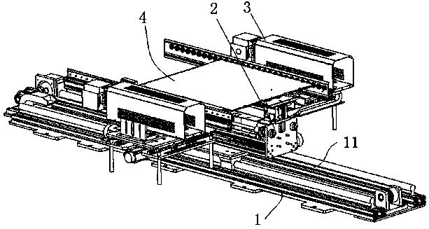
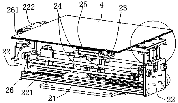
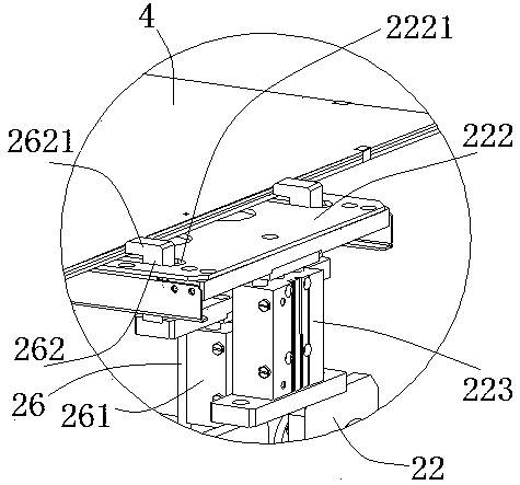
[0030] like Figure 1-4 , a laser glue cutting machine for PCB glue cutting, including a frame 1, the frame 1 is provided with a first guide rail 11, and the first guide rail 11 is movably provided with a transfer mechanism; The transfer mechanism includes a bottom plate 21 movably arranged on the first guide rail 11, and the bottom plate 21 is drivingly connected with the first driving mechanism arranged on the frame 1 for driving the bottom plate 21 along the The first guide rail 11 reciprocates, the front and rear ends of the bottom plate 21 are provided with brackets 22, the bracket 22 is provided with a support plate 222 for placing the PCB board 4, and the frame 1 is also provided with a rotating lift mechanism 2, the rotary lifting mechanism 2 is arranged between the...


PUM


Abstract

The invention relates to a laser tape cutting machine for PCB tape cutting and belongs to the field of PCBs. The laser tape cutting machine comprises a rack. A first guide rail is arranged on the rack, and a moving mechanism is movably arranged on the first guide rail. The moving mechanism comprises a bottom plate movably arranged on the first guide rail. The bottom plate is in driving connectionwith a first driving mechanism arranged on the rack, and the first driving mechanism is used for driving the bottom plate to move along the first guide rail in a reciprocating manner. Supports are correspondingly arranged at the front end and the rear end of the bottom plate. A support plate used for containing the PCBs is arranged on each support. A rotating lifting mechanism is arranged on the rack. Laser cutters are arranged on the rack, and the laser cutters are located on the left side and the right side of the first guide rail. According to the laser tape cutting machine for PCB tape cutting, the laser is adopted to cut the adhesive tape on the PCBs, and compared with a mode of using a cutting blade for cutting the adhesive tape, by the adoption of the laser tape cutting machine, a blade does not need to be replaced, the cutting efficiency is improved, the situation that the adhesive tape cannot be cut off is avoided, and the cutting quality and the cutting efficiency can be improved effectively.

Description

technical field [0001] The invention relates to the field of PCBs, in particular to a laser cutting machine for glue cutting of PCBs. Background technique [0002] In the PCB industry, before the PCB drilling process, the PCB stack needs to be pinned and the edge is covered with glue. After the drilling is completed, the PCB stack needs to be disassembled, pinned, glued, and separated. At present, the rubber tapping equipment on the market after PCB dismantling is still unstable, and the rubber tapping adopts the blade cutting method. Due to the short service life of the blade, it needs to be replaced every 1 hour, and four of them need to be replaced each time, which takes about 15 minutes; extremely The production efficiency is greatly reduced; in addition, the blade holder adopts an elastic mechanism, which is prone to continuous cutting of rubber and cutting, causing PCB to be lifted and injured during the subsequent process of manipulator separation, and the equipment a...

Claims


Application Information

Patent Timeline
Patent Type & Authority Applications(China)
IPC IPC(8): B23K26/38B23K26/402B23K26/70
CPCB23K26/38B23K26/402B23K26/702
Inventor 杨健何茂水罗冬张旭
Owner HUIZHOU CHENGTAI AUTOMATION TECH CO LTD
Learn More