
Refrigeration device and refrigeration device operation method

A refrigeration device and operating method technology, applied in the direction of refrigeration and liquefaction, refrigerators, refrigeration components, etc., can solve the problems of reduced heat exchange rate, decreased refrigeration capacity of refrigeration devices, and greater impact

Inactive Publication Date: 2020-03-24
MITSUBISHI ELECTRIC CORP
View PDF8 Cites 0 Cited by
  • Summary
  • Abstract
  • Description
  • Claims
  • Application Information

AI Technical Summary

Problems solved by technology

Thus, when uneven frosting occurs in the evaporator, even if the overall amount of frosting is the same as in the case of uniform frosting, the space between the fins on the inlet side of the evaporator will be blocked by frost at an early stage. , resulting in a decrease in the heat exchange rate
Therefore, there is a problem that the deterioration of the heat exchange rate due to non-uniform frosting has a greater influence than the improvement of the heat exchange rate due to the convection of the refrigerant and the heat source medium, so that the heat transfer rate in the evaporator The evaporating pressure drops, the COP of the refrigeration unit and the cooling capacity of the refrigeration unit decrease

Method used


Image

  • Refrigeration device and refrigeration device operation method
  • Refrigeration device and refrigeration device operation method
  • Refrigeration device and refrigeration device operation method

Examples


Embodiment approach 1

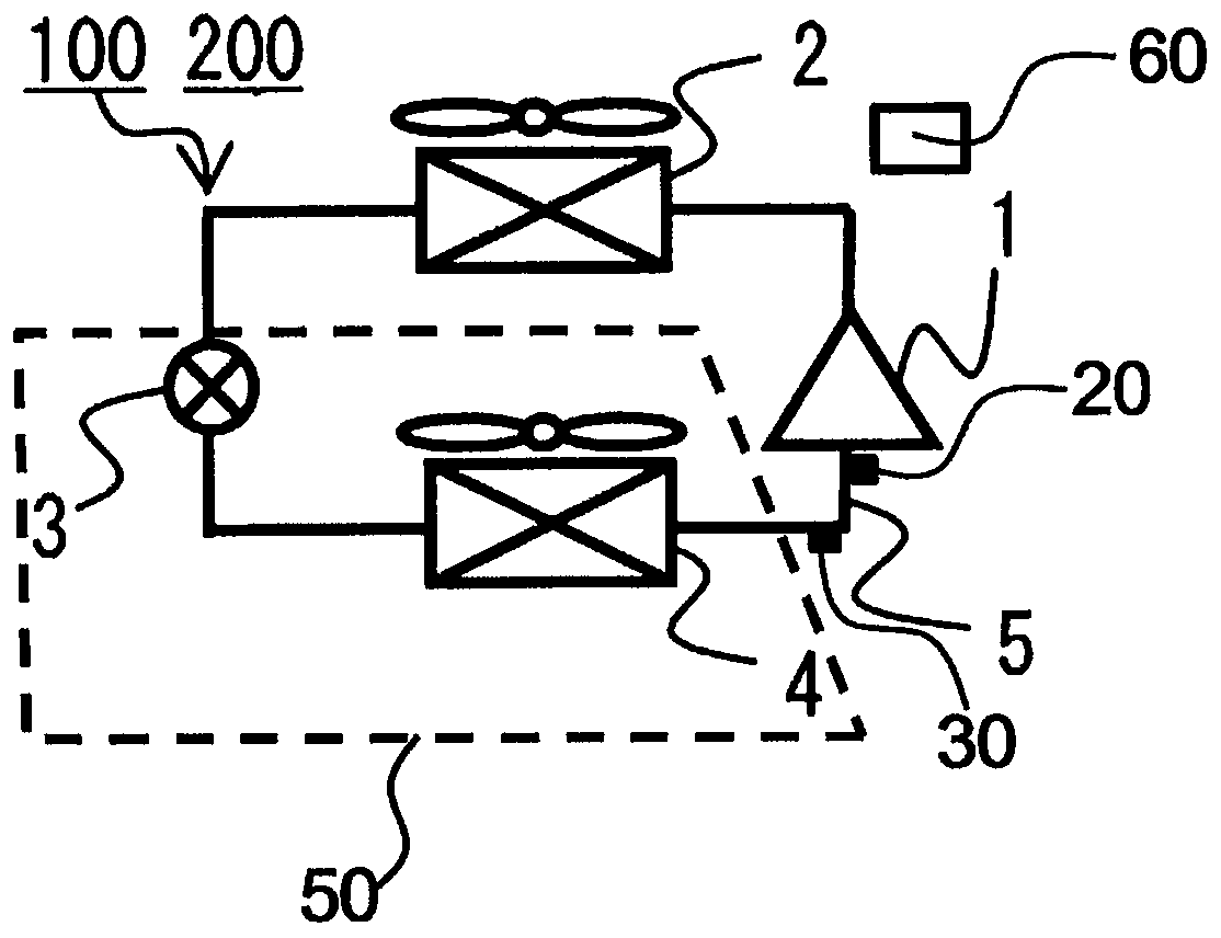
[0018] figure 1 It is a schematic diagram showing the overall configuration of the refrigeration device 100 according to Embodiment 1 of the present invention. In addition, the same code|symbol is attached|subjected to the same part or a corresponding part in each figure. Such as figure 1 As shown, the refrigeration device 100 according to Embodiment 1 is formed by sequentially connecting the compressor 1 , the condenser 2 , the decompression device 3 , and the evaporator 4 through the refrigerant piping 5 . The refrigeration device 100 has a refrigeration cycle in which a refrigerant circulates in the order of the compressor 1 , the condenser 2 , the decompression device 3 , the evaporator 4 , and the compressor 1 . The control unit 60 controls each device constituting the refrigeration device 100 .

[0019] (compressor 1)

[0020] The compressor 1 sucks in refrigerant, compresses it into a high-temperature and high-pressure gas state, and discharges it. For example, the...

Embodiment approach 2

[0065] The refrigeration device 100 according to the second embodiment is different from the refrigeration device 100 according to the first embodiment in that the composition of the refrigerant circulating in the refrigeration device 100 is limited. In Embodiment 2, description will be made focusing on changes from Embodiment 1. FIG.

[0066] The zeotropic mixed refrigerant circulating in the refrigeration device 100 of Embodiment 2 is a mixed refrigerant of R32, R125, R134a, R1234yf, and carbon dioxide, and the ratio of R32 is X R32 36wt%, the proportion of R125 X R125 30wt%, R134a ratio X R134a 14wt%, the proportion of R1234yf X R1234yf 14wt%, the proportion of carbon dioxide X co2 is 6wt%. The following effects can be obtained by using such a refrigerant.

[0067]First, although each single refrigerant has physical properties that are advantages or disadvantages, by mixing a plurality of refrigerants, the disadvantages can be reduced and the advantages can be increase...


PUM


Abstract

This invention aims at preventing unbalanced frost formation in a refrigeration device using a non-azeotropic refrigerant mixture having a temperature gradient so as to prevent a decline in COP for the refrigeration device and in the refrigeration capacity of the refrigeration device. This refrigeration device is characterized by comprising a refrigeration cycle in which a compressor, a condenser,a pressure reducing device, and an evaporator are connected with refrigerant piping and in which a refrigerant circulates, wherein the refrigerant is a non-azeotropic refrigerant mixture in which a plurality of refrigerant types are mixed, and the evaporator reduces the internal pressure of the piping in conformity with the direction of refrigerant flow during an evaporation process in accordancewith the temperature gradient of the non-azeotropic refrigerant mixture.

Description

technical field [0001] The present invention relates to a refrigerating device, in particular to a refrigerating device using a non-azeotropic mixed refrigerant and a method for operating the refrigerating device. Background technique [0002] Conventionally, there is known a refrigerating apparatus having a refrigeration cycle in which a refrigerant is circulated by connecting an evaporator, a compressor, a condenser, and a decompression device through lines through which the refrigerant circulates. [0003] In addition, it is known that in refrigeration devices such as air conditioners and refrigerators, the direction in which the heat exchange air flows and the direction in which the refrigerant flows are opposed to each other for the heat exchanger functioning as an evaporator, and the heat exchange air Convective flow with refrigerant reduces heat exchange loss and improves performance (for example, refer to Patent Document 1). [0004] On the other hand, as a refriger...

Claims


Application Information

Patent Timeline
IPC IPC(8): F25B1/00F25B39/02
CPCF25B1/00F25B39/02
Inventor 森田久登田中学
Owner MITSUBISHI ELECTRIC CORP
Learn More