
Apparatus for spinning yarn and method for heating same

A technology of heating chamber and metering device is applied in the field of spinning device, which can solve the problems of uneven temperature distribution and achieve the effect of uniform temperature

Inactive Publication Date: 2017-09-26
OERLIKON TEXTILE GMBH & CO KG
View PDF6 Cites 0 Cited by
  • Summary
  • Abstract
  • Description
  • Claims
  • Application Information

AI Technical Summary

Problems solved by technology

If there is too much condensation in the heating chamber, it can cause uneven temperature distribution

Method used


Image

  • Apparatus for spinning yarn and method for heating same
  • Apparatus for spinning yarn and method for heating same
  • Apparatus for spinning yarn and method for heating same

Examples


Embodiment Construction

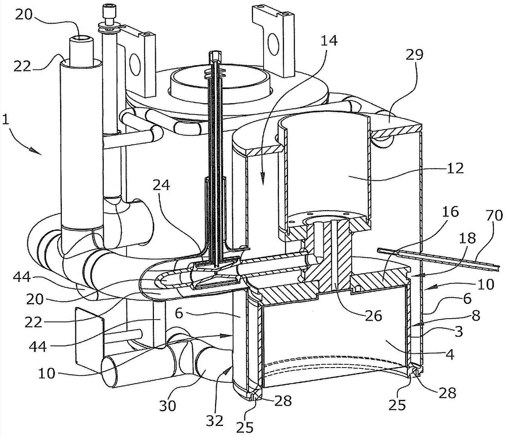
[0038] figure 1 A device 1 for spinning yarn is schematically shown. The melt is melted in the melting device 2 and supplied to the metering device 12 via a melt supply line 20 . The melt from the metering device is forced through spinning nozzles arranged in the nozzle package 4 and drawn off in the form of filaments or fibers 35 . After leaving the spinning nozzle, the filaments are cooled, for example by air, in a blow-on shaft 27 and the cooled fibers 33 are then wound on drums or placed in containers. The filaments can be withdrawn directly or at least after a period of time in a withdrawal device not shown here. The melting device 2, the melt supply line 20 and the metering device 12 are part of the melt supply device. The nozzle package is a holder for the spinning nozzle.

[0039] figure 2 is a detail showing a part of the device 1 for spinning thread. The melting device 2 is not shown, nor is the blowing shaft 27 shown. A nozzle package 4 with at least one spi...


PUM


Abstract

In an apparatus (1) for spinning threads, having at least one melt feeding device, at least one spinneret pack (4) with at least one spinneret, wherein a first housing (8) with a first housing wall (3) is arranged around the spinneret pack (4), a second housing (10) with a second housing wall (6) is arranged around the first housing (8), wherein a heating space (14) filled with a gaseous heating medium is arranged between the first and the second housings (8, 10), wherein the first and the second housing walls (3, 6) bound the heating space (14), provision is made for the heating space (14) to have a housing base (28) which is formed so as to drop obliquely away from the first housing wall (3) in the direction of the second housing wall (6), such that condensate that has collected on the housing base (28) drains in the direction of the second housing wall (6).

Description

technical field [0001] The invention relates to a device for spinning yarn and a method for heating a device for spinning fibres. Background technique [0002] Known devices for spinning yarn comprise at least one melt supply and at least one nozzle package with at least one spinning nozzle (spinning nozzle) for spinning yarn. The nozzle package is heated, thereby heating the spinning nozzle. In order to obtain good thread properties it is important to keep the temperature of the nozzle package and the temperature distribution within the spinning nozzle within as narrow limits as possible. It is also known from the prior art to arrange a first housing with a first housing wall around the nozzle package. A second housing having a second housing wall may be arranged around the first housing. A heating chamber filled with a gaseous heating medium is arranged between the first housing and the second housing, the walls of the first housing and the second housing delimiting the...

Claims


Application Information

Patent Timeline
IPC IPC(8): D01D1/09
CPCD01D1/09
Inventor 赖纳·蒂策
Owner OERLIKON TEXTILE GMBH & CO KG
Learn More