
Flange joint

A flange joint and flange installation technology, applied in the direction of flange connection, pipe/pipe joint/pipe fitting, through components, etc., can solve the problems of radial movement of pipe joints, leakage of medium in the pipeline, loss of sealing effect, etc. Achieve the effect of avoiding deformation and damage of gaskets, prolonging service life and simple structure

Pending Publication Date: 2020-03-24
安徽欣景隆轨道车辆装备有限公司 +1
View PDF0 Cites 0 Cited by
  • Summary
  • Abstract
  • Description
  • Claims
  • Application Information

AI Technical Summary

Problems solved by technology

[0004] 1. During the operation of the train, there are high-frequency vibrations in the working environment of the pipeline on the train. The vibration acts on the mechanical structures such as pipelines and pipe joints, and the sealing gasket will be squeezed inward accordingly, causing mechanical fatigue and damage. Easy to break and lose sealing effect;
[0005] 2. The above-mentioned upper-frequency vibration during the train operation directly acts on the pipe joints, which may easily cause radial movement between the pipe joints, resulting in loose threads, resulting in loose connection between the pipe joints, resulting in pipeline Internal medium leakage
[0006] 3. Although the joint structure provided by our company in the prior application 2019109363681 can limit the radial movement between pipe joints, its structure is relatively complicated. During the installation process, the positioning part and the limit device need to be respectively placed on the joint parts The outer circumference of the joint, press the positioning part to realize the fastening of the bolts in the joint part
In use, although the structure is fixed and has a good sealing effect, it is easily restricted by the narrow installation environment and is inconvenient to install

Method used


Image

  • Flange joint
  • Flange joint
  • Flange joint

Examples


Embodiment Construction

[0029] In order to make the purpose and technical solutions of the embodiments of the present invention more clear, the technical solutions of the embodiments of the present invention will be clearly and completely described below in conjunction with the drawings of the embodiments of the present invention. Apparently, the described embodiments are some, not all, embodiments of the present invention. Based on the described embodiments of the present invention, all other embodiments obtained by persons of ordinary skill in the art without creative efforts shall fall within the protection scope of the present invention.

[0030] Those skilled in the art can understand that, unless otherwise defined, all terms (including technical terms and scientific terms) used herein have the same meaning as commonly understood by those of ordinary skill in the art to which this invention belongs. It should also be understood that terms such as those defined in commonly used dictionaries shoul...


PUM


Abstract

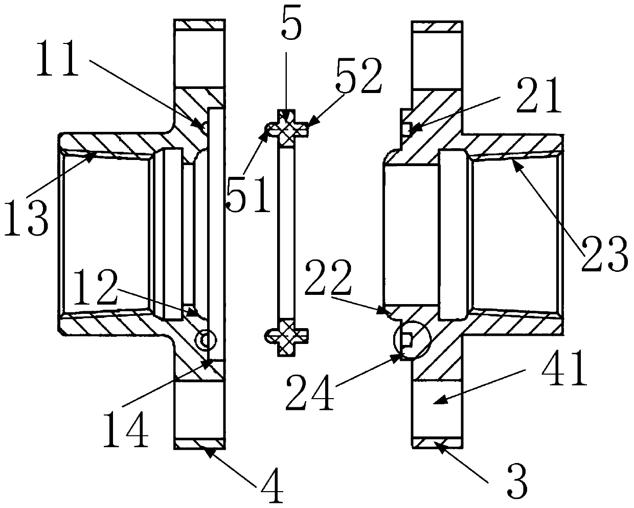
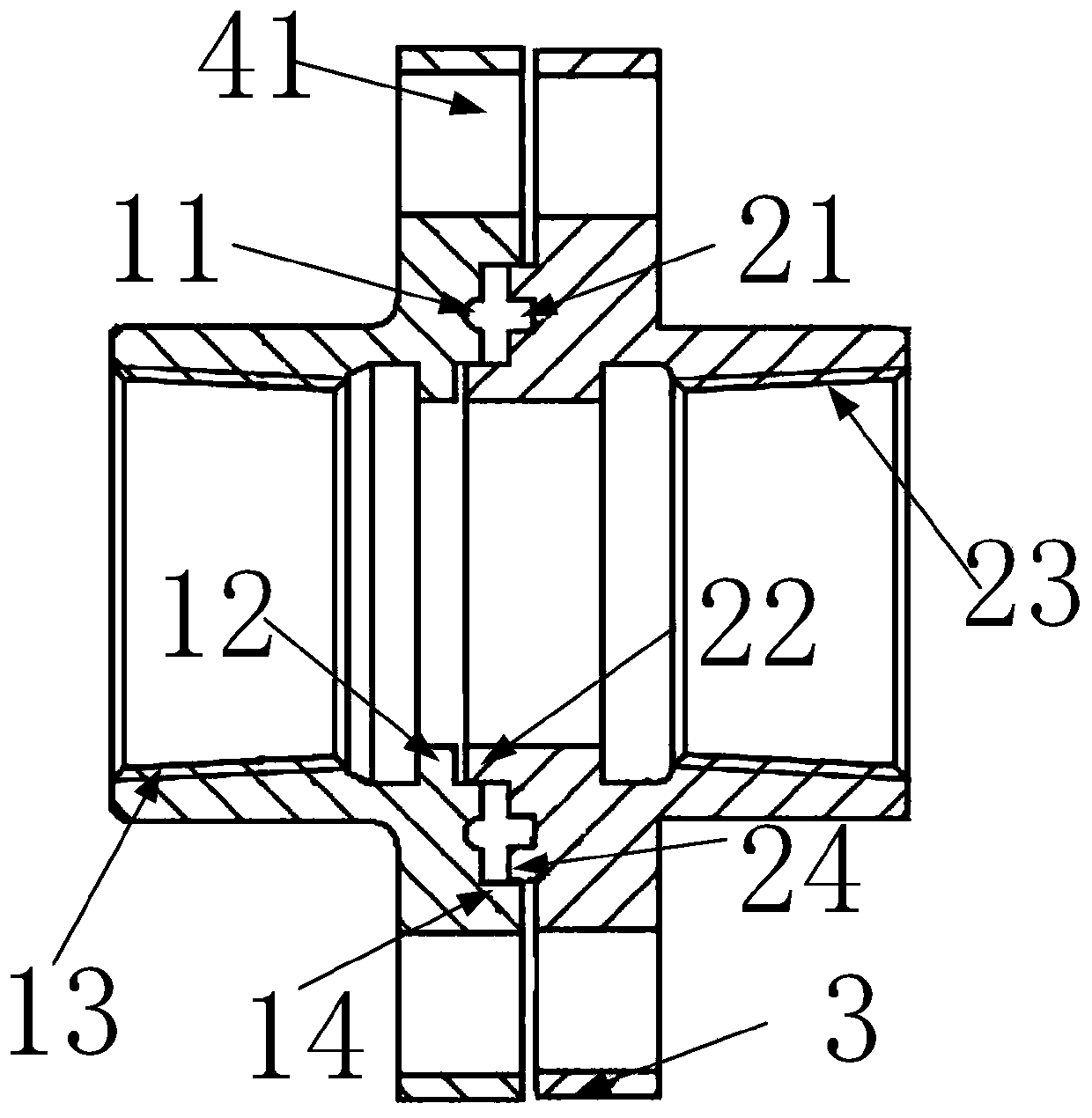
The invention relates to a flange joint. The flange joint comprises a first pipe joint and a second pipe joint; flange installation pieces are arranged on the peripheries of the two pipe joints respectively; the two flange installation pieces are fixedly connected through a fastener; and therefore, the radial or circumferential movement of the pipe joints is limited. Sealing grooves are formed inthe end portions of the two pipe joints respectively; and a gasket is arranged between the two sealing grooves to achieve the sealing of the pipe joints. The inner ring of each sealing groove is provided with a positioning ring, and the positioning rings abut against each other to prevent the sealing ring from directing contact with a medium circulating in the joints. The flange joint is simple instructure. The internal structures of the pipe joints are designed; the fixed connection of the pipe joints can be achieved just through the fastener; the relative movement of the pipe joint structures can be effectively limited; and the gasket can be effectively protected, and the service life of the gasket is prolonged.

Description

technical field [0001] The invention relates to the field of train components, in particular to a flange joint. Background technique [0002] The pipes on the vehicle need to be connected through pipe joints. The sealing of the connecting parts between the existing pipe joints is realized only through threads and sealing washers. [0003] There are following problems in the way of sealing between pipelines on the existing train: [0004] 1. During the operation of the train, there are high-frequency vibrations in the working environment of the pipeline on the train. The vibration acts on the mechanical structures such as pipelines and pipe joints, which will correspondingly squeeze the sealing gasket inward, causing it to cause mechanical fatigue and damage Easy to break and lose sealing effect; [0005] 2. The above-mentioned high-frequency vibration during the train operation directly acts on the pipe joints, which may easily cause radial movement between the pipe joint...

Claims


Application Information

Patent Timeline
Patent Type & Authority Applications(China)
IPC IPC(8): F16L23/032F16L23/22
CPCF16L23/032F16L23/22
Inventor 尹俊李建勇张其武王建辉
Owner 安徽欣景隆轨道车辆装备有限公司
Learn More