Head cooling device for emergency nursing

A cooling device and head technology, which is applied in the direction of heating appliances for treatment, cooling appliances for treatment, contraceptives, etc., can solve the problems of low cooling effect, complicated operation, unsuitable for rapid cooling of emergency patients, etc., to achieve Good cooling effect

Inactive Publication Date: 2020-03-24
THE AFFILIATED HOSPITAL OF QINGDAO UNIV
View PDF11 Cites 3 Cited by
  • Summary
  • Abstract
  • Description
  • Claims
  • Application Information

AI Technical Summary

Problems solved by technology

However, the cooling effect of this device is low, and the operation is complicated, so it is not suitable for rapid cooling of emergency patients.

Method used


Image

  • Head cooling device for emergency nursing
  • Head cooling device for emergency nursing
  • Head cooling device for emergency nursing

Examples


Embodiment 1

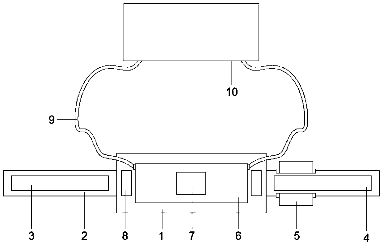
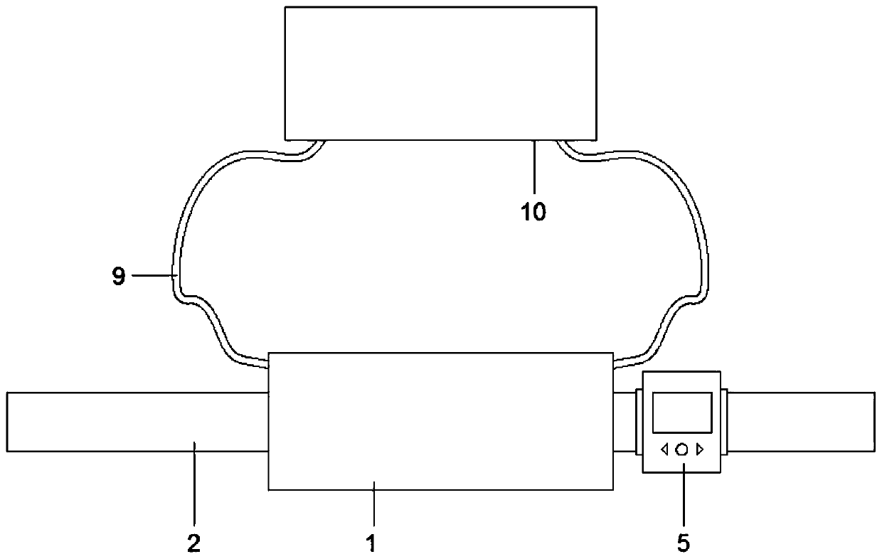
[0028] Embodiment 1: The water bag 6 is connected to the transmission pipe 9 through the connecting pipe, and the connecting pipe is connected with a blocking cap through a plastic connecting rod, and the blocking cap is screwed to the connecting pipe. Pipeline 9, after freezing the water bag 6, paste heat-dissipating stickers or alcohol stickers on the cooling sticker limit plate 7, use two sets of straps 2 to tie on the head, and use the male Velcro sticker 3 and the female Velcro sticker 24 to cool down The forehead belt 1 is located on the forehead to cool down the patient's head, combined with two sets of temperature sensors 8 to detect the temperature of the forehead, and the measured temperature results are displayed on the display screen 5 in real time, which is convenient for visually observing the cooling condition of the patient's head.

Embodiment 2

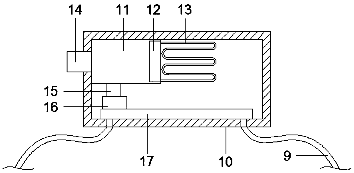
[0029]Embodiment 2: unscrew the cap on the connecting pipe of the water bag 6 and connect it to the transmission pipe 9, and then use two sets of straps 2 to tie the head to the forehead through the male velcro 3 and the female velcro 24 to make the forehead band cool 1 is located on the forehead, the condensing box 10 is prevented from being hung on the bedside or on the wall, the evaporator 12 and the air pump 16 are started, and the air is drawn through the intake pipe 14, and the evaporator 12 evaporates the condensing agent to absorb heat, so that the gas in the air-conditioning chamber 11 When the temperature drops, the air pump 16 pumps out the air in the cold air chamber 11, and discharges the cold air into the liquid accumulation tank 17 through the outlet pipe with a one-way valve, and the air pressure in the liquid collection tank 17 changes to realize the liquid state in the water bag 6. The flow of the polymer cooling gel, the cold air enters the water bag 6 throug...


PUM


Abstract

The invention discloses a head cooling device for emergency nursing in the technical field of medical equipment. The device comprises a cooling forehead band bandages are sewn in the centers of the left side and the right side of the cooling forehead band; a male attaching tape and a female attaching tape are respectively sewn on the left and right groups of bandages through needles and threads; and a display screen is clamped to the left side of the bandage at the right side. A water bag is arranged in the center of the back face of the cooling forehead band; a cooling paste limiting plate isfixedly arranged in the center of the surface of the water bag; temperature sensors are glued to the centers of the left side and the right side of the back face of the cooling forehead band; and thetops of the left side face and the right side face of the water bag are sleeved with transmission pipelines through connecting pipes. According to the invention, after the water bag is directly frozen, a heat dissipation paste is pasted on the cooling paste limiting plate; the cooling forehead band is bound to the forehead for cooling; blocking caps arranged on a water bag connecting pipe can bescrewed off and connected with the transmission pipelines; an air extracting pump extracts air in a cold air chamber and discharges the air into a liquid accumulation box to realize circulating flowing of liquid in the water bag. Therefore, the head of a patient can be cooled and the cooling effect is good.

Description

technical field [0001] The invention relates to the technical field of medical equipment, in particular to a head cooling device for emergency care. Background technique [0002] The emergency medicine department or emergency medicine center is the department with the most intensively ill patients, the most types of diseases, and the heaviest rescue and management tasks in the hospital. It is the only way for all emergency patients to be admitted to the hospital for treatment. Fever symptoms are common in the emergency department, and physical cooling should be the first choice for fever. In addition to drug treatment, the easiest, most effective and safe cooling method for patients with high fever is to use 25%-50% alcohol to wipe the body to cool down. The concentration is not easy to control, long-term use of high-concentration alcohol is easy to stimulate the skin to absorb a large amount of water in the epidermis, and increases the workload of medical staff and reduces ...

Claims


Application Information

Patent Timeline
Patent Type & Authority Applications(China)
IPC IPC(8): A61F7/10A61F7/00
CPCA61F7/10A61F7/0053A61F2007/0056A61F2007/0095A61F2007/0007
Inventor 代月光范学宾杨洁婷王慧芳沈霞
Owner THE AFFILIATED HOSPITAL OF QINGDAO UNIV
Why Eureka
Try Eureka