
Glucometer connector production equipment

A production equipment and connector technology, applied in the field of blood glucose machine connector production equipment, can solve problems such as backward efficiency and stability, inconvenient machine adjustment, lack of product size testing, etc., and achieve the effect of convenient debugging operation and stable production

Pending Publication Date: 2020-03-20
SUZHOU E CONN TECH
View PDF0 Cites 1 Cited by
  • Summary
  • Abstract
  • Description
  • Claims
  • Application Information

AI Technical Summary

Problems solved by technology

[0002] Nowadays, with the improvement of medical treatment, the range of use of blood glucose machine connector products is getting wider and larger, and the required production capacity and quality are getting higher and higher. In this case, it is necessary to vigorously develop automation equipment to To meet the needs and reduce labor costs, and to update the original equipment, the original low-cost blood glucose machine connector products are mostly assembled by hand with jigs. Compared with pure manual assembly, although the original production capacity has been improved, the efficiency of the equipment is stable. And control has fallen behind with the development. The pin insertion mechanism of the previous generation of automatic equipment has strict requirements on materials and lacks stability. It is inconvenient to change the product number and adjust the machine. Lack of product size testing, maintenance and debugging are difficult and time-consuming. More, based on the above defects and deficiencies, it is necessary to improve the existing technology and design a blood glucose machine connector production equipment

Method used


Image

  • Glucometer connector production equipment
  • Glucometer connector production equipment
  • Glucometer connector production equipment

Examples


Embodiment Construction

[0029] The preferred embodiments of the present invention will be described in detail below in conjunction with the accompanying drawings, so that the advantages and features of the invention can be more easily understood by those skilled in the art, so as to define the protection scope of the present invention more clearly.

[0030] see Figure 1 to Figure 12 , the embodiment of the present invention includes:

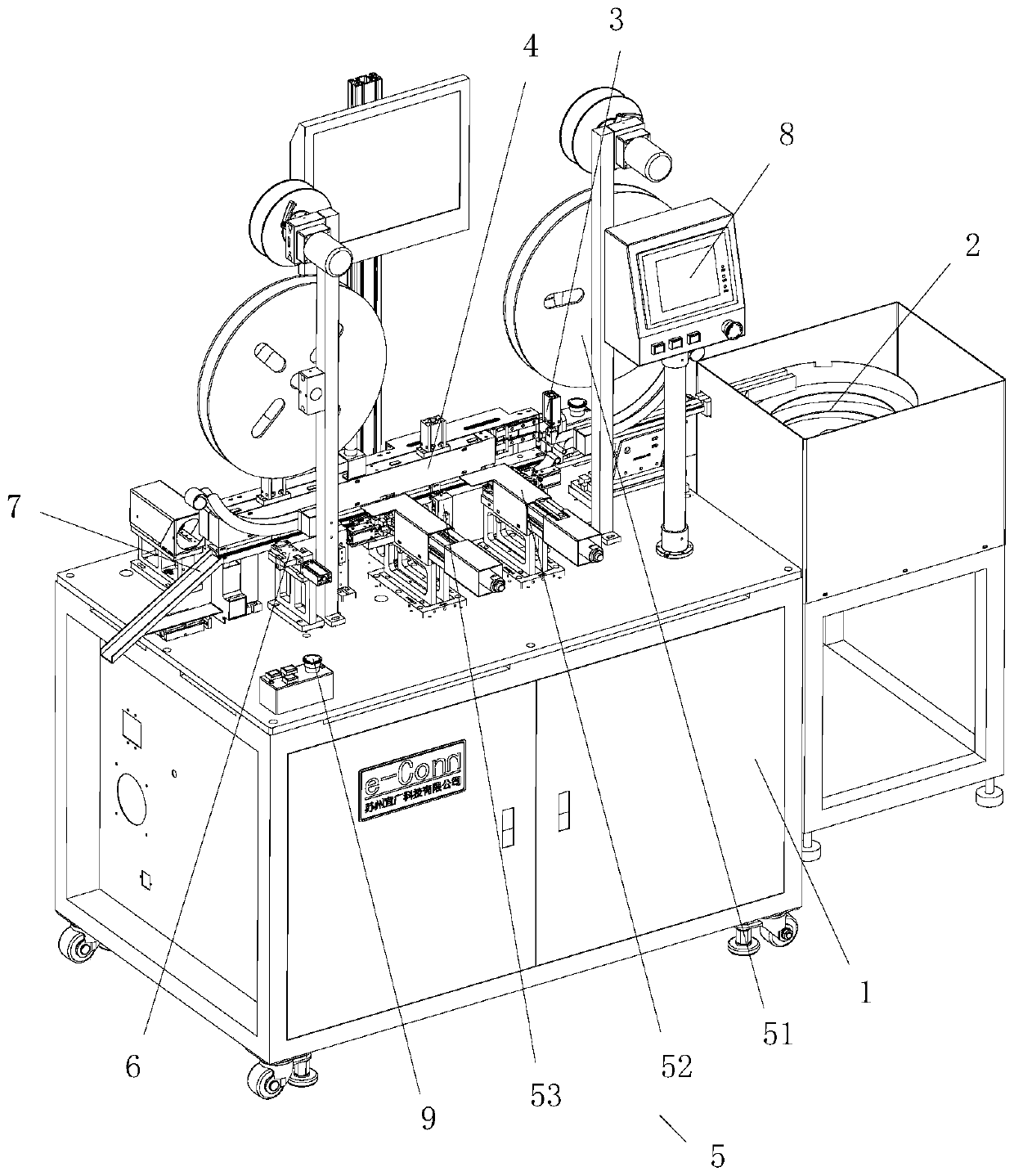
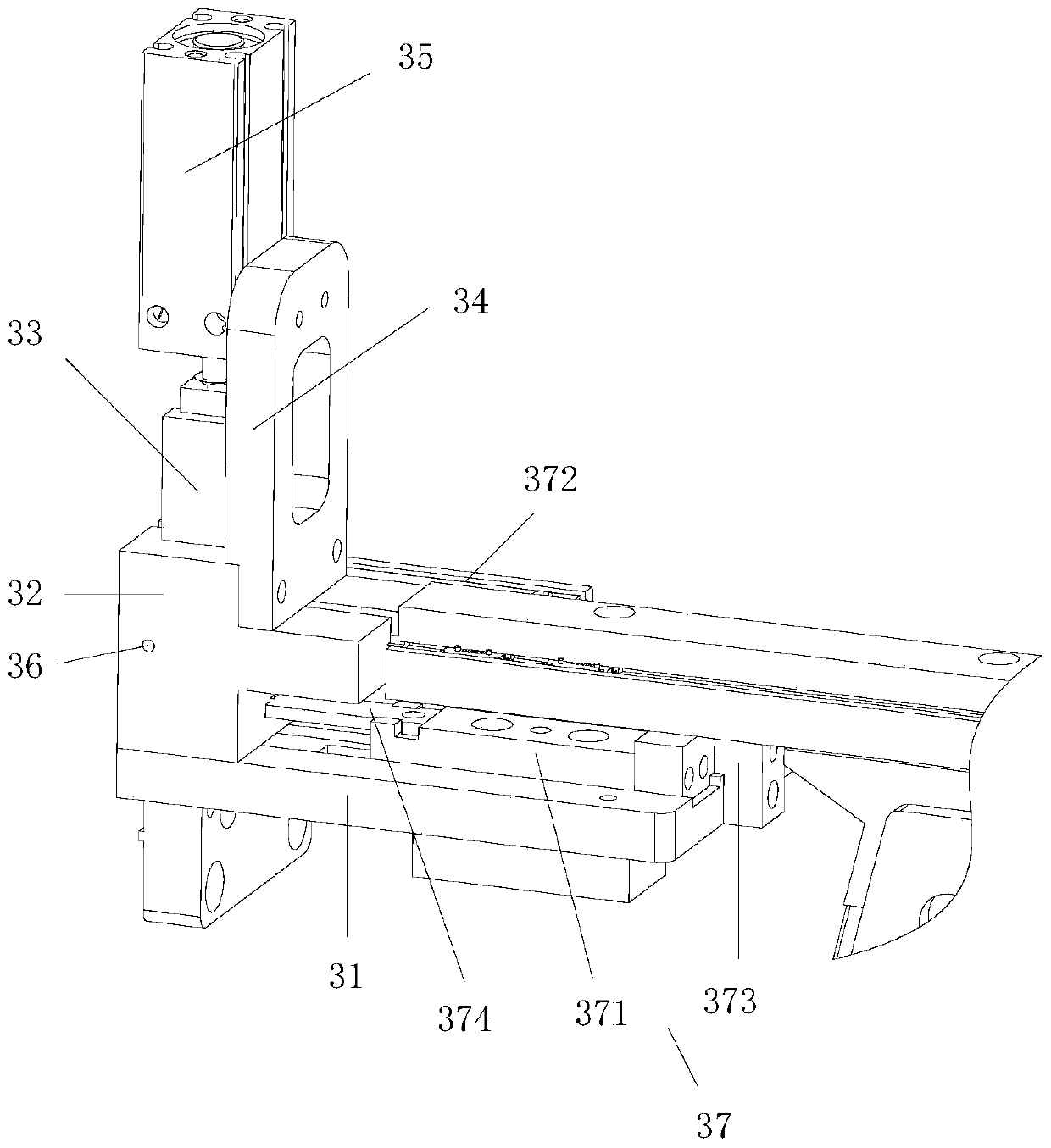
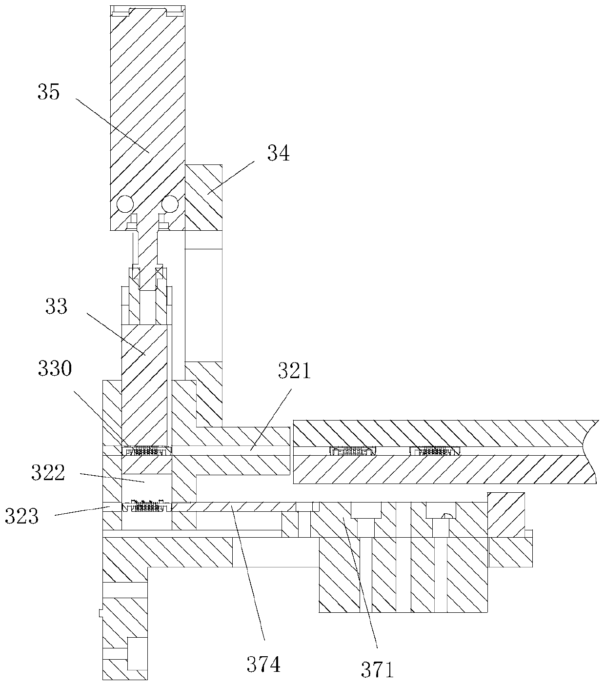
[0031]A blood sugar machine connector production equipment, which includes a rubber core feeding device 2 arranged on a frame 1, an elevator type dislocation mechanism 3, a linear transplanting processing flow channel mechanism 4, a hugging cutter Inserting and sweeping mechanism 5, coplanarity shaping mechanism 6, discharge mechanism 7, man-machine operation 8 and operation button 9, elevator-type dislocation mechanism 3 upper rubber core is transported to the linear transplanting processing channel mechanism through elevator-type dislocation mechanism 3 4. Two grou...


PUM


Abstract

The invention discloses production equipment for a blood glucose machine connector. The glucometer connector production equipment comprises a rubber core feeding device, an elevator type staggering mechanism, a linear transplanting and processing flow channel mechanism, a conveying, holding, cutting, inserting and sweeping mechanism, a coplanarity shaping mechanism, a discharging mechanism and a man-machine operation and operation button which are arranged on a rack, rubber cores on the elevator type staggering mechanism are conveyed to the linear transplanting machining runner mechanism through the elevator type staggering mechanism, the two sets of conveying, holding, cutting, inserting and sweeping mechanisms are used for inserting long terminals and short terminals into the rubber cores correspondingly, and after product assembling is completed, the coplanarity shaping mechanism is used for shaping, and the rubber cores are discharged through the discharging mechanism. By means ofthe mode, the mechanism is compact in structure, stable in operation, capable of achieving independent discharging, capable of achieving unified material moving and positioning, capable of enabling all stations to work in sequence, free of mutual interference, uniform in layout, capable of enabling operation conditions of all mechanisms to be observed easily, convenient to maintain and capable ofconveniently replacing materials at all positions.

Description

technical field [0001] The invention relates to the technical field of industrial machinery, in particular to a production equipment for a blood glucose machine connector. Background technique [0002] Nowadays, with the improvement of medical treatment, the range of use of blood glucose machine connector products is getting wider and larger, and the required production capacity and quality are getting higher and higher. In this case, it is necessary to vigorously develop automation equipment to To meet the needs and reduce labor costs, and to update the original equipment, the original low-cost blood glucose machine connector products are mostly assembled by hand with jigs. Compared with pure manual assembly, although the original production capacity has been improved, the efficiency of the equipment is stable. And control has fallen behind with the development. The pin insertion mechanism of the previous generation of automatic equipment has strict requirements on material...

Claims


Application Information

Patent Timeline
Patent Type & Authority Applications(China)
IPC IPC(8): H01R43/20B07C5/10
CPCB07C5/10H01R43/20H01R2201/12
Inventor 王发帅陈文
Owner SUZHOU E CONN TECH
Learn More