High-repetition-frequency high-energy nanosecond pulse laser and using method thereof
A pulsed laser and high-energy technology, which is applied to lasers, laser components, phonon exciters, etc., can solve problems such as low repetition frequency, harsh operating environment requirements, and difficult amplification, and achieve good calibration and amplification effects
- Summary
- Abstract
- Description
- Claims
- Application Information
AI Technical Summary
Problems solved by technology
Method used
Image
Examples
Embodiment 1
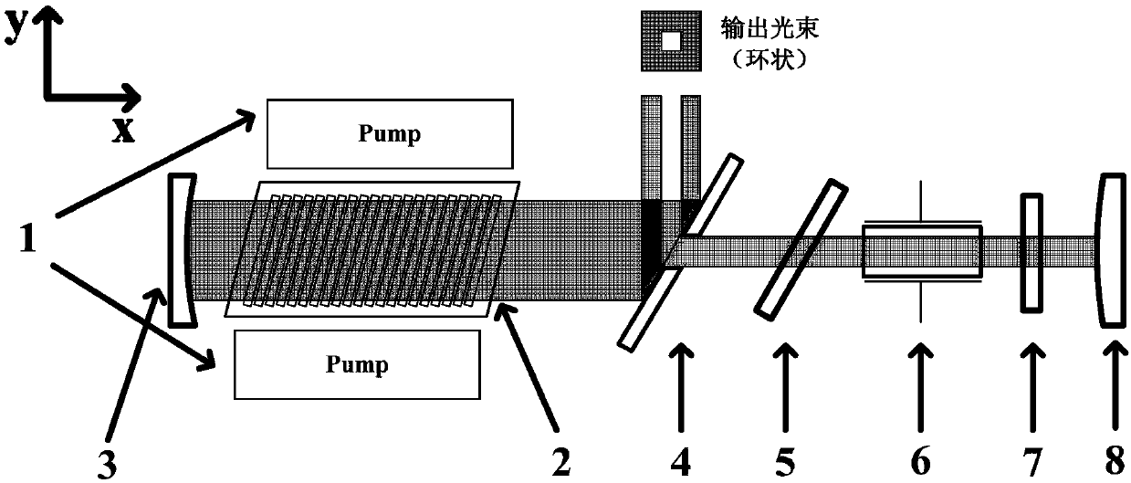
[0022] The first embodiment of the present invention is as figure 1 As shown, the present invention provides a high-repetition-frequency high-energy nanosecond-level pulsed laser (polarizer transmissive electro-optic Q-switching), including:
[0023] Pump laser 1; laser gain cell 2, concave mirror 3, convex mirror 8, scraper mirror 4, thin film polarizer 5, Pockels cell 6, and λ / 4 wave plate 7, concave mirror 3 and convex reflector The magnification M=2 of mirror 8, the cavity length (the cavity length is the optical distance between the concave reflector and the convex reflector) 1500mm, the radius of curvature of the concave reflector and the convex reflector are respectively 6000mm and 3000mm; The light transmission direction of the oscillating laser in cell 2 is defined as the x-axis direction, the light transmission direction of the pump light is defined as the y-axis direction, and the direction of the z-axis is determined according to the right-hand rule; the gain medium ...
Embodiment 2
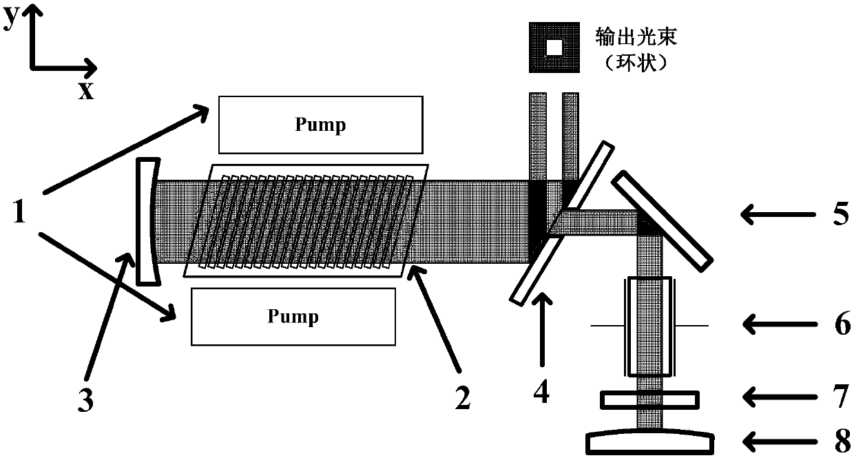
[0025] The second embodiment of the present invention is as figure 2 As shown, the present invention provides a high-repetition-frequency high-energy nanosecond pulse laser (polarizer reflective electro-optic Q-switching), only the electro-optic Q-switching part is different, and the others are the same as in Embodiment 1. The electro-optic Q-switching device adopts polarizer reflective electro-optic Q-switching; along the x-axis direction, a concave reflector 3, a laser gain pool 2, a scraper mirror 4, and a film polarizer 5 are arranged in sequence. After the film polarizer 5, along the In the y-axis direction, a Pockels cell 6, a λ / 4 wave plate 7 and a convex reflector 8 are arranged in sequence, the concave surface of the concave reflector 3 faces the laser gain pool, and the convex surface of the convex reflector 8 faces the λ / 4 wave plate; The electro-optic Q-switching process is: the gain medium Nd:YAG crystal is pumped by the pump laser 1, emits natural light, and aft...
Embodiment 3
[0027] The third embodiment of the present invention is as figure 1 As shown, the present invention provides a high-repetition-frequency high-energy nanosecond-level pulsed laser (polarizer transmissive electro-optic Q-switching), and only the gain medium part in the pump laser 1 and the laser gain cell 2 is different from that of Embodiment 1. different, everything else is the same.
[0028] The pumping laser beam output by the pumping laser 1 has a wavelength of 940nm, a repetition rate ≥ 200Hz, and a single-array pumping average power of 10kW. Medium Yb: inside YAG ceramics, which provides gain for the formation of laser, the output laser wavelength is 1030nm, the output spot is an annular hollow spot on the outside (60mm×60mm) and inside (30mm×30mm), single pulse energy ≥ 20J, repetition frequency ≥200Hz.
PUM
| Property | Measurement | Unit |
|---|---|---|
| wavelength | aaaaa | aaaaa |
| angle of incidence | aaaaa | aaaaa |
| length | aaaaa | aaaaa |
Abstract
Description
Claims
Application Information
 - R&D
- Intellectual Property
- Life Sciences
- Materials
- Tech Scout
- Unparalleled Data Quality
- Higher Quality Content
- 60% Fewer Hallucinations
Browse by: Latest US Patents, China's latest patents, Technical Efficacy Thesaurus, Application Domain, Technology Topic, Popular Technical Reports.
© 2025 PatSnap. All rights reserved.Legal|Privacy policy|Modern Slavery Act Transparency Statement|Sitemap|About US| Contact US: help@patsnap.com


