
Cutting and polishing equipment for plastic-wood plate

A board and plastic wood technology, applied in the field of plastic wood board cutting and polishing equipment, can solve the problems of fixed plastic wood board, rough and unequal cutting surface, and achieve the effect of smooth cutting surface and time saving.

Active Publication Date: 2020-03-13
江西新森岱塑木科技有限公司
View PDF7 Cites 17 Cited by
  • Summary
  • Abstract
  • Description
  • Claims
  • Application Information

AI Technical Summary

Problems solved by technology

[0005] In order to overcome the disadvantage that the existing technology cannot fix the wood-plastic board, the wood-plastic board may shake, causing the cutting surface of the wood-plastic board to be rough and uneven, the technical problem of the present invention is: to provide a wood-plastic board that can prevent the Wood-plastic sheet cutting and polishing equipment with smoother cutting surface

Method used


Image

  • Cutting and polishing equipment for plastic-wood plate
  • Cutting and polishing equipment for plastic-wood plate
  • Cutting and polishing equipment for plastic-wood plate

Examples


Embodiment 1

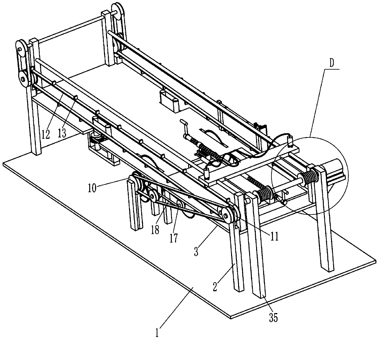
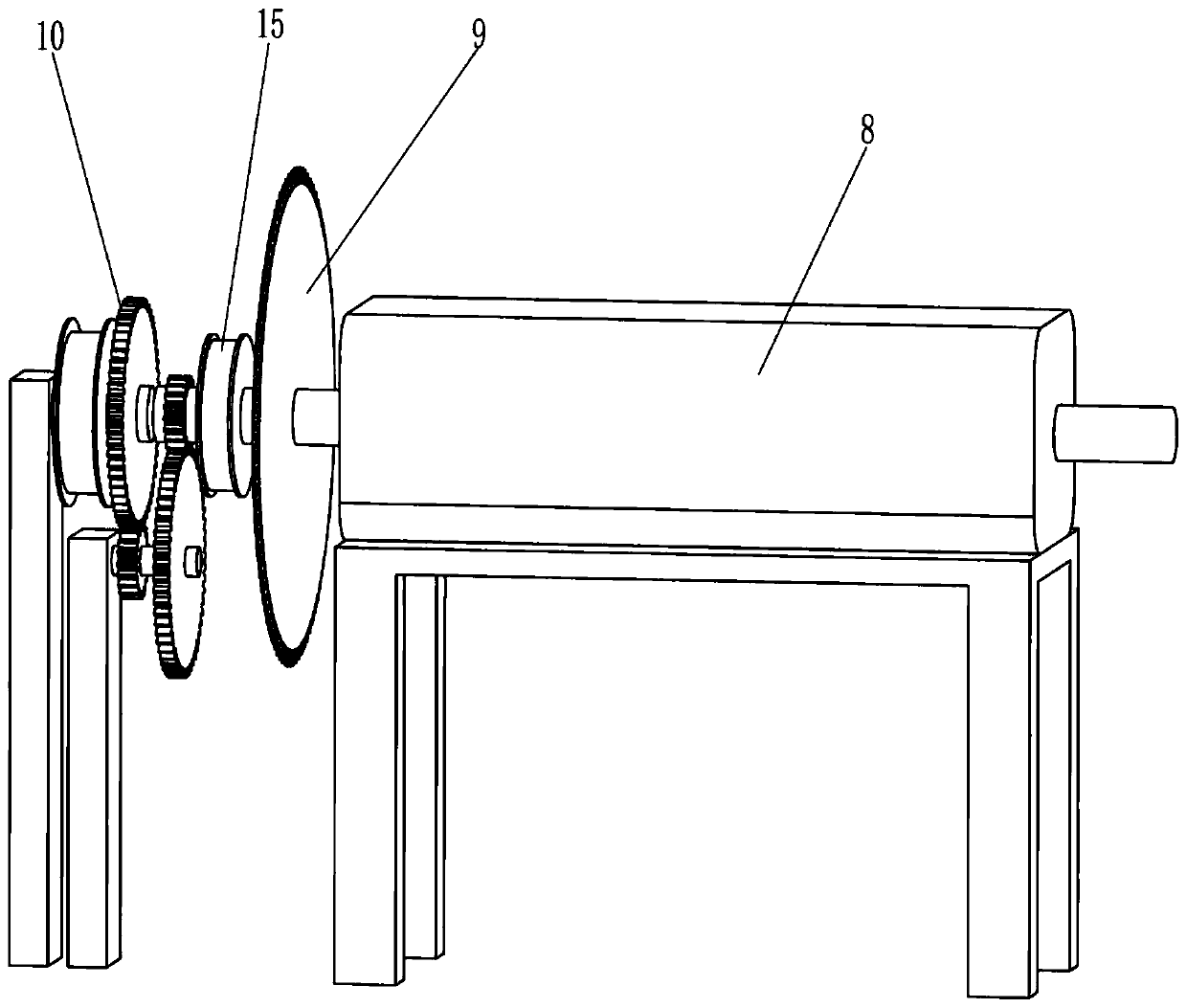
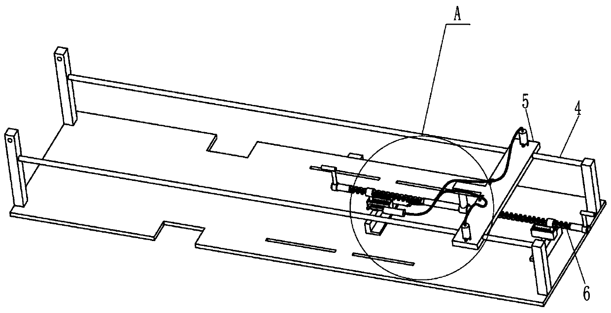
[0033] A wood-plastic plate cutting and polishing equipment, refer to Figure 1-13 , including a bottom plate 1, a first bracket 2, a placement plate 3, a first slide bar 4, a slide plate 5, a transmission block 51, a clamping assembly 6, a biaxial motor 8, a first cutting saw 9, a transmission assembly 10, a first Transmission wheel 11, the first transmission belt 12, the first push block 13, polishing assembly 14 and cutting assembly, the left and right sides of bottom plate 1 top all are equipped with first support 2 by bolt, are connected between the first support 2 of left and right sides Place plate 3 and two first slide bars 4, place plate 3 is positioned at below two first slide bars 4, two first slide bars 4 slide type is provided with slide plate 5, slide plate 5 front and rear all have The two openings are provided with transmission blocks 51, the top of the bottom plate 1 is connected with a mounting frame, the top of the mounting frame is equipped with a double-ax...

Embodiment 2

[0042] On the basis of embodiment 1, with reference to Figure 4 , Figure 5 , Figure 6 and Figure 14 , also includes a clutch assembly 7, the clutch assembly 7 includes a first compression cylinder 701, an intake valve 702, an outlet valve 703, a first push rod 704, a first piston 705, an air pipe 706, a second compression cylinder 707, a second The piston 708 and the second spring 709 are connected with the first compression cylinder 701 on the front and rear sides of the housing 604 on the left side, the two first compression cylinders 701 are connected with the intake valve 702, and the first sliding sleeve 603 on the left side The front and rear sides are connected with a first push rod 704, the first push rod 704 runs through the left housing 604, the first compression cylinder 701 is provided with a first piston 705, and the first push rod 704 runs through the left side of the first compression cylinder 701. side and is connected with the left side of the first pis...


PUM


Abstract

The invention relates to cutting and polishing equipment, and in particular relates to the cutting and polishing equipment for a plastic-wood plate. The invention provides the cutting and polishing equipment capable of preventing the plastic-wood plate from shaking and making the cutting surface of the plastic-wood plate more smooth for the plastic-wood plate. The cutting and polishing equipment for the plastic-wood plate includes a base plate, first supports, a placing plate, first sliding rods and the like; and the first supports are fixedly connected to two sides of the top of the base plate, the placing plate and the first sliding rods are fixedly connected between the first supports on two sides, and the placing plate is placed below the first sliding rods. According to the equipment,the plastic-wood plate can be fixed by a clamping component to prevent the plastic-wood plate from shaking, the plastic-wood plate can be polished by the polishing component, so that the cutting surface of the plastic-wood plate is smoother, a clutch component can replace manual operation, so that the equipment can be more automated; and a sliding plate can be pulled back by a small motor, so that the sliding plate can be pulled back quickly, and the time can be saved.

Description

technical field [0001] The invention relates to cutting and polishing equipment, in particular to a cutting and polishing equipment for plastic wood boards. Background technique [0002] Wood-plastic board is a high-tech green and environmentally friendly new composite material made of wood as the basic material, plus plastics and processing aids, mixed evenly, and then heated and extruded by mold equipment. It can replace wood and plastics. , In the production process of plastic wood board, it is necessary to cut the plastic wood board. [0003] In the prior art, there are devices that can cut wood-plastic boards, such as the patent with the publication number CN205415751U, which discloses a wood-plastic board cutting device, including a workbench, and a conveyor belt is provided in the middle of the upper end surface of the workbench. A pole is fixedly connected to the workbench by screws, a carriage is fixed on the upper part of the pole, a telescopic cylinder is provide...

Claims


Application Information

Patent Timeline
IPC IPC(8): B27B5/06B27B5/22B27B5/29B27B29/02B27G19/02B24B21/04B24B21/18B24B41/06B24B55/00
CPCB24B21/04B24B21/18B24B41/06B24B55/00B27B5/06B27B5/222B27B5/29B27B29/02B27G19/02
Inventor 严正席应旺张明静
Owner 江西新森岱塑木科技有限公司
Learn More