


Quick Research
Generate reliable direction feasibility study reports for your R&D in just a few steps.

Technical Q&A
Discover and master advanced knowledge NOW. Basics, ideas, possibilities, all at once.

Find Solutions
As an expert in R&D theories, this can generate solutions to your technical problems instantly.

Evaluate Feasibility
Analyze your overall solution with one click, know your potential R&D risks in advance.

Monitor Landscape
Get weekly tech updates, stay abreast of the latest tech innovations and key insights.
Fault positioning method, device and system
A fault location and fault technology, applied in instruments, error detection/correction, calculation, etc., can solve the problems of inability to obtain fault information in time and low positioning accuracy, so as to reduce the cost of positioning, improve the accuracy of positioning, and improve the efficiency of positioning Effect
- Summary
- Abstract
- Description
- Claims
- Application Information
AI Technical Summary
Problems solved by technology
Method used
Image

Examples
Embodiment 1
[0034] According to an embodiment of the present application, an embodiment of a fault location method is provided. It should be noted that the steps shown in the flowcharts of the drawings can be executed in a computer system such as a set of computer-executable instructions, and, although A logical order is shown in the flowcharts, but in some cases the steps shown or described may be performed in an order different from that shown or described herein.
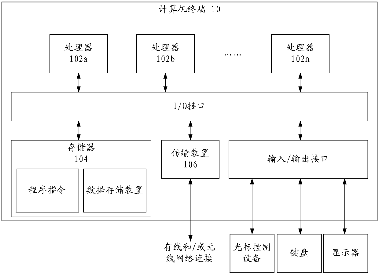
[0035] The method embodiment provided in Embodiment 1 of the present application may be executed in a mobile terminal, a computer terminal, or a similar computing device. figure 1 A block diagram of a hardware structure of a computer terminal (or mobile device) for implementing a fault location method is shown. Such as figure 1 As shown, the computer terminal 10 (or mobile device 10) may include one or more (shown by 102a, 102b, ..., 102n in the figure) processor 102 (the processor 102 may include but not limited to a micro...
Embodiment 2
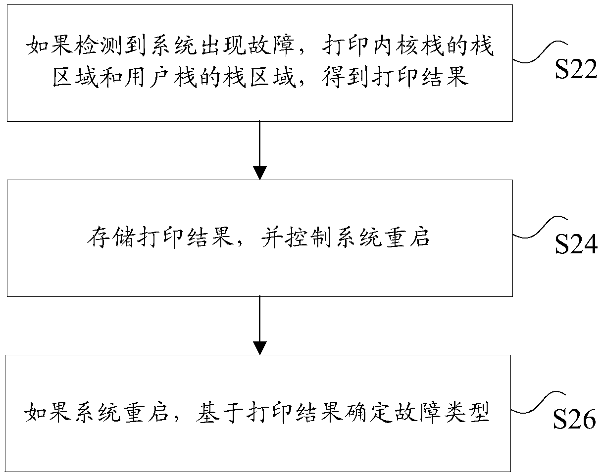
[0108] According to an embodiment of the present application, a fault location device for implementing the above fault location method is also provided, such as Figure 7 As shown, the apparatus 700 includes: a printing module 702 , a storage module 704 and a determination module 706 .
[0109] Wherein, the printing module 702 is used to print the stack area of the kernel stack and the stack area of the user stack to obtain the print result if a system failure is detected; the storage module 704 is used to store the print result and control the restart of the system; the determination module 706 is used to If the system restarts, determine the type of failure based on the printed results.
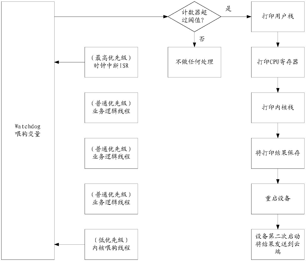
[0110] Specifically, the above-mentioned system may be a Linux operating system deployed in an intelligent router in a public area, and the intelligent router is implemented by hardware based on MIPS CPU architecture and a Linux kernel. The watchdog program can be used to detect whethe...
Embodiment 3
[0159] According to an embodiment of the present application, a fault location system is also provided, including:
[0160] processor; and
[0161] The memory, connected to the processor, is used to provide the processor with instructions for processing the following processing steps: if a fault is detected in the system, print the stack area of the kernel stack and the stack area of the user stack to obtain the print result; store the print result, and control System restart; if the system restarts, determine the fault type based on the printed results.
[0162] The method provided in the above-mentioned embodiment 3 of the present application, if a system failure is detected, print the stack area of the kernel stack and the stack area of the user stack, obtain the print result, store the print result, and control the system to restart. If the system restarts successfully, further Determine the fault type based on the printing results, so as to realize the purpose of...
PUM
 Abstract
Description
Claims
Application Information
 - R&D Engineer
- R&D Manager
- IP Professional
- Industry Leading Data Capabilities
- Powerful AI technology
- Patent DNA Extraction
Browse by: Latest US Patents, China's latest patents, Technical Efficacy Thesaurus, Application Domain, Technology Topic, Popular Technical Reports.
© 2024 PatSnap. All rights reserved.Legal|Privacy policy|Modern Slavery Act Transparency Statement|Sitemap|About US| Contact US: help@patsnap.com