


Quick Research
Generate reliable direction feasibility study reports for your R&D in just a few steps.

Technical Q&A
Discover and master advanced knowledge NOW. Basics, ideas, possibilities, all at once.

Find Solutions
As an expert in R&D theories, this can generate solutions to your technical problems instantly.

Evaluate Feasibility
Analyze your overall solution with one click, know your potential R&D risks in advance.

Monitor Landscape
Get weekly tech updates, stay abreast of the latest tech innovations and key insights.
Machine tool bed with saddle oil return channel
A technology of oil return channel and bed, which is applied in the field of bed with saddle oil return channel, which can solve the problems of wear, debris generation, increased wear of saddle components and turret components, etc., and achieve high cooling efficiency, Filter effect improvement, filter effect high effect
- Summary
- Abstract
- Description
- Claims
- Application Information
AI Technical Summary
Problems solved by technology
Method used
Image

Examples
Embodiment 1
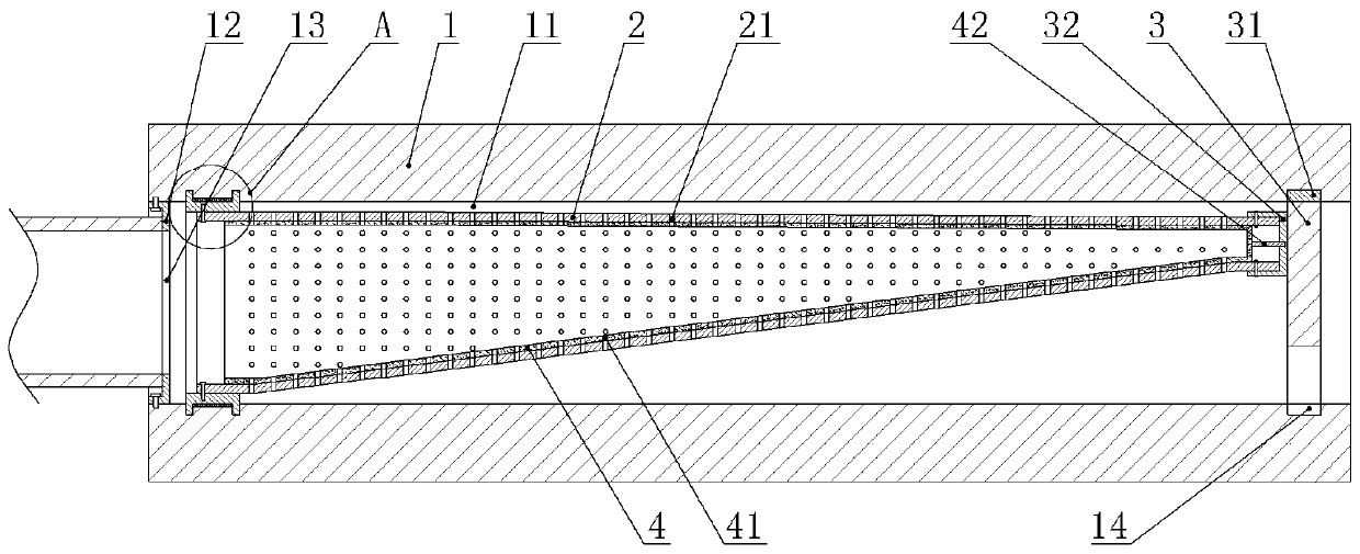
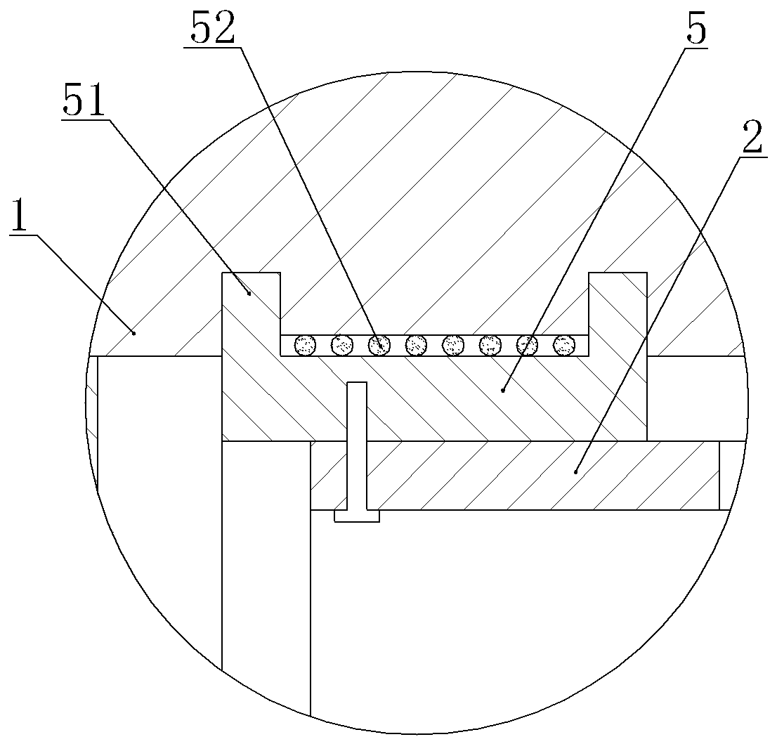
[0034] A bed with a saddle oil return channel, such as figure 1 with figure 2 As shown, the bed 1 is vertically provided with an oil return channel, and the upper end of the oil return channel communicates with the lubricating channel. The bed 1 is provided with a filter channel 11 located below the oil return channel. The filter channel 11 is arranged horizontally. The right end of the filter channel 11 is connected to an oil pump. The filter channel 11 is equipped with an axial flow blade 3 and a hose 2 along the axial direction. , The hose 2 in this embodiment is made of metal braid, and the hose 2 is provided with a number of filter holes 21 . The axial flow blade 3 is located on the right side of the hose 2, and the right end of the filter channel 11 in this embodiment is provided with an annular rotating groove 14, and three sliding blocks 31 are arranged in the rotating groove 14, and the three sliding blocks 31 are respectively connected with the axial flow type. Th...
Embodiment 2
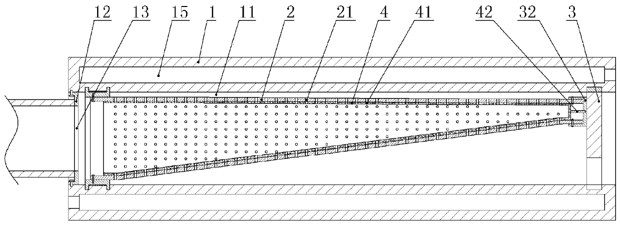
[0040] On the basis of Example 1, such as image 3 As shown, the machine tool in this embodiment is provided with a cooling channel 15 , and the cooling channel 15 is arranged along the axial direction of the filtering channel 11 , and the cooling channel 15 in this embodiment is annular and located on the outer periphery of the filtering channel 11 . The right end of the cooling passage 15 in this embodiment is the liquid inlet end, and the left end is the liquid outlet end. In practice, the left and right ends of the cooling passage 15 are connected with water outlet pipes and water inlet pipes.
[0041] When the machine tool in this embodiment is working, cooling water is added into the cooling passage 15 from the water inlet pipe at the same time, and the cooling water in the cooling passage 15 is discharged from the water outlet pipe. The heat in the lubricating oil in the filtering passage 11 is transferred to the cooling water in the cooling passage 15, and then dischar...
PUM
 Abstract
Description
Claims
Application Information
 - R&D Engineer
- R&D Manager
- IP Professional
- Industry Leading Data Capabilities
- Powerful AI technology
- Patent DNA Extraction
Browse by: Latest US Patents, China's latest patents, Technical Efficacy Thesaurus, Application Domain, Technology Topic, Popular Technical Reports.
© 2024 PatSnap. All rights reserved.Legal|Privacy policy|Modern Slavery Act Transparency Statement|Sitemap|About US| Contact US: help@patsnap.com